I recently bought an Apple ][c off eBay. Been looking to get one of the old Apple systems for a while now. I guess this will be a blog of my misadventures with it. Either it will be toast or I will have a nice like new system and a bunch of games that I used to play. Do I know what I am doing? Who knows. Is this going to be a good blog? Probably not, I skip over quite a few things and probably wont document absolutely everything.
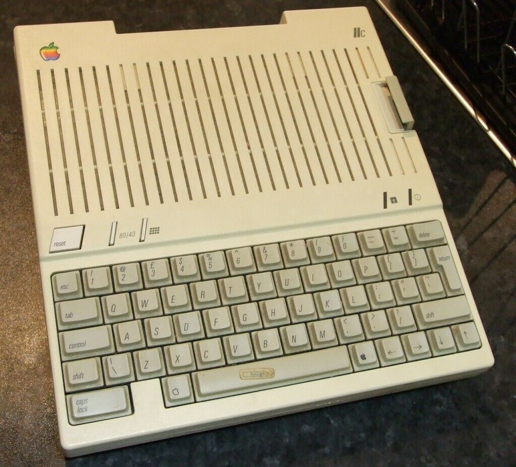
This one came working with no power supply, the original set of disks and manuals which was a surprise. The listing had a link to a youtube video which showed the system working, which was a neat idea.
Not having an CRT, i initially used an composite to HDMI converter and ran the video into a monitor. This only gives a black and white display however, something to do with how the Apple ][c generates the colours.
Good enough for now though. I also had a small LCD TV with RCA inputs, same result.
Step 1: Destroy it.
First point of call was to try and make a power supply for it. These computers have an internal DC-DC converter, and can take in from 9 to 20VDC. This is pretty nifty. They seemed to design it as a portable unit that can run from a battery.
I butchered an old universal laptop power supply, which can put out either 16 or 19v. I bought some cheap and nasty power plugs, 7 pin female DIN style and wired it up. Something went wrong though, and after initially having a play with one of the disks, it fails to boot up correctly, and sits at a screen of random characters. It appears you can reset it, but the system is not operating correctly.
Also, it was working quite strangely. When powering it off, the power would seem to surge and then the laptop power supply would switch off.
Time to open it up and investigate the power supply. Assuming caps might be dead, bugs in it or something else.
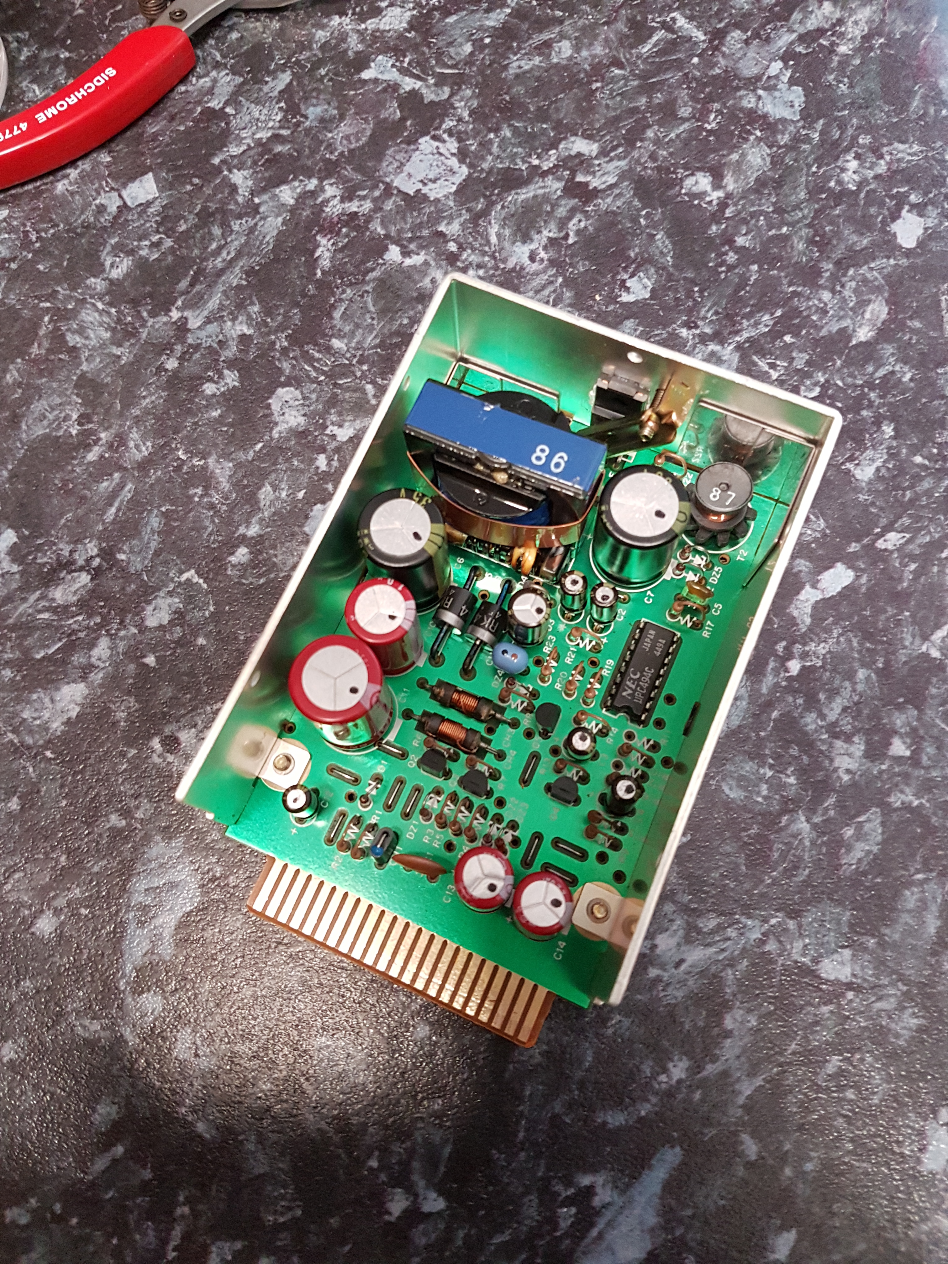
Connected this up to my bench supply, and tested each output. It seems to be working fine. It outputs 12v, 5v and -12v, and can be switched on and off.
Worth noting I found a service manual for the Apple ][c, and it has some basic schematics for the mainboard, and the pin-outs for the power supply.
Replaced the paste on the component at the back, and plonked it back in.
From now on I have been powering the unit straight from the bench supply. There is a handy reverse polarity protection diode, and I have been putting the supply voltage on that for now until I can make a decent supply.
The unit seems to be drawing quite a bit more power than it should, and still isn’t working. More than 2amps at 20v it seems.
The 5v rail is sitting just under 5v, and is used to supply all the chips. Some may have died during the power issues? Some felt a bit warm.
I tried reseating all the socketed ones to no avail.
Next I sprayed some isopropyl on them while running to see which ones are getting hot. And wouldn’t you know it.
MRD1, MRD7, ARD4 and ARD7 are quite toasty. They haven’t dragged the 5v rail down, but are boiling off the isopropyl much faster than other chips on the board. In a couple of seconds.
Step 2: Fix it.
I desoldered each of these RAM chips using a combination of a solder sucker, wick and a lot of flux. I borrowed ARD5 and ARD6, to put down in MRD1 & MRD7. All without destroying the board, pads or the chips. I also ordered a bunch of new chips, as some others might be bad. I also ordered a new ROM, as I thought that might be bad before doing the moist test.

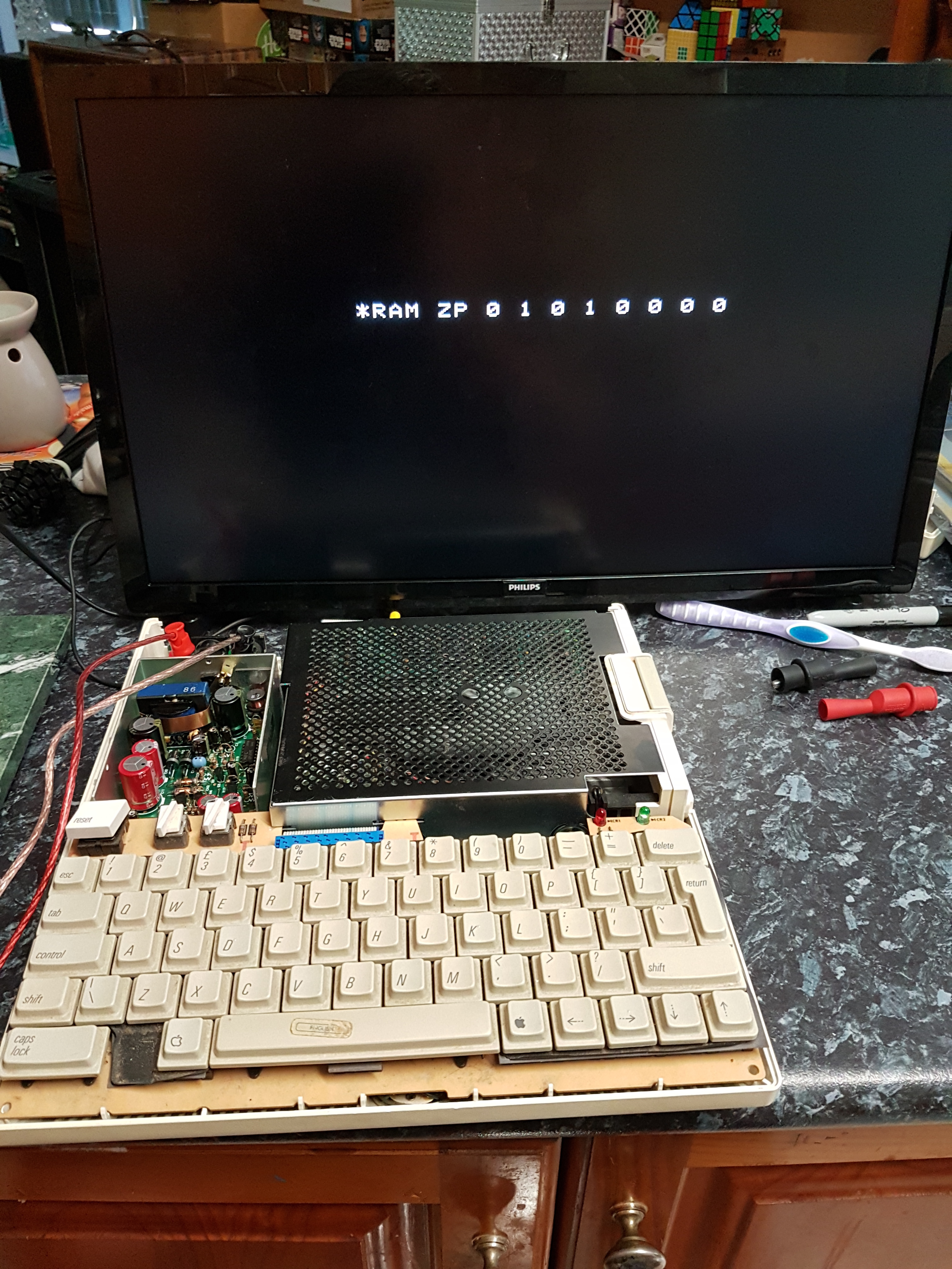
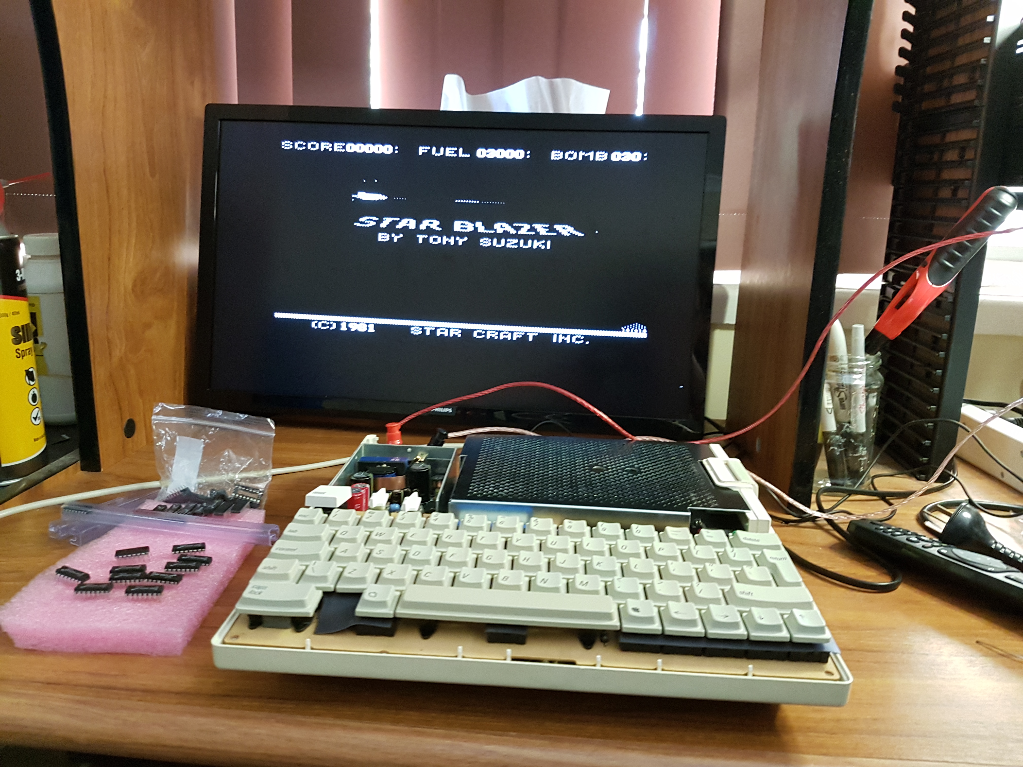
So, after all that, I am happy to report it is booting again! It will even boot a disk, but programs tend to crash now. Perhaps due to bad ram, or lack of a few RAM chips.
You can initiate a Built-In Test (BIT) by holding open & close apple while booting. This flashes a few random screens up and them reports the following info:
Step 3: Clean keyboard.
The keyboard, while functional, has some sticky keys and is a bit grubby. Also like the 8 Bit guy’s Apple ][c, the rubber sheet is falling to bits.
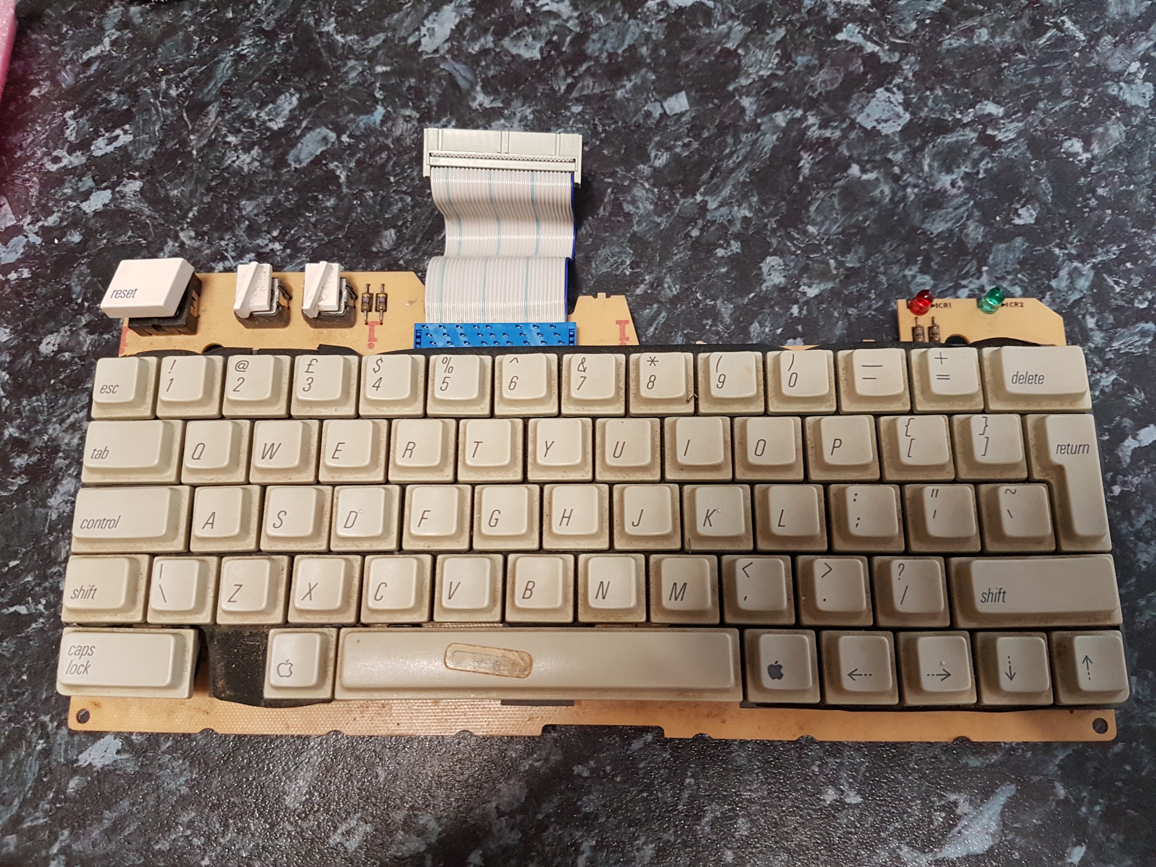
I used a pair of small angled pliers to pry off all the keys, removed the rubber sheets, and scrubbed it down with isopropyl.
I scrubbed the keys down in a bowl with dish soap, removed the english sticker on the space bar.
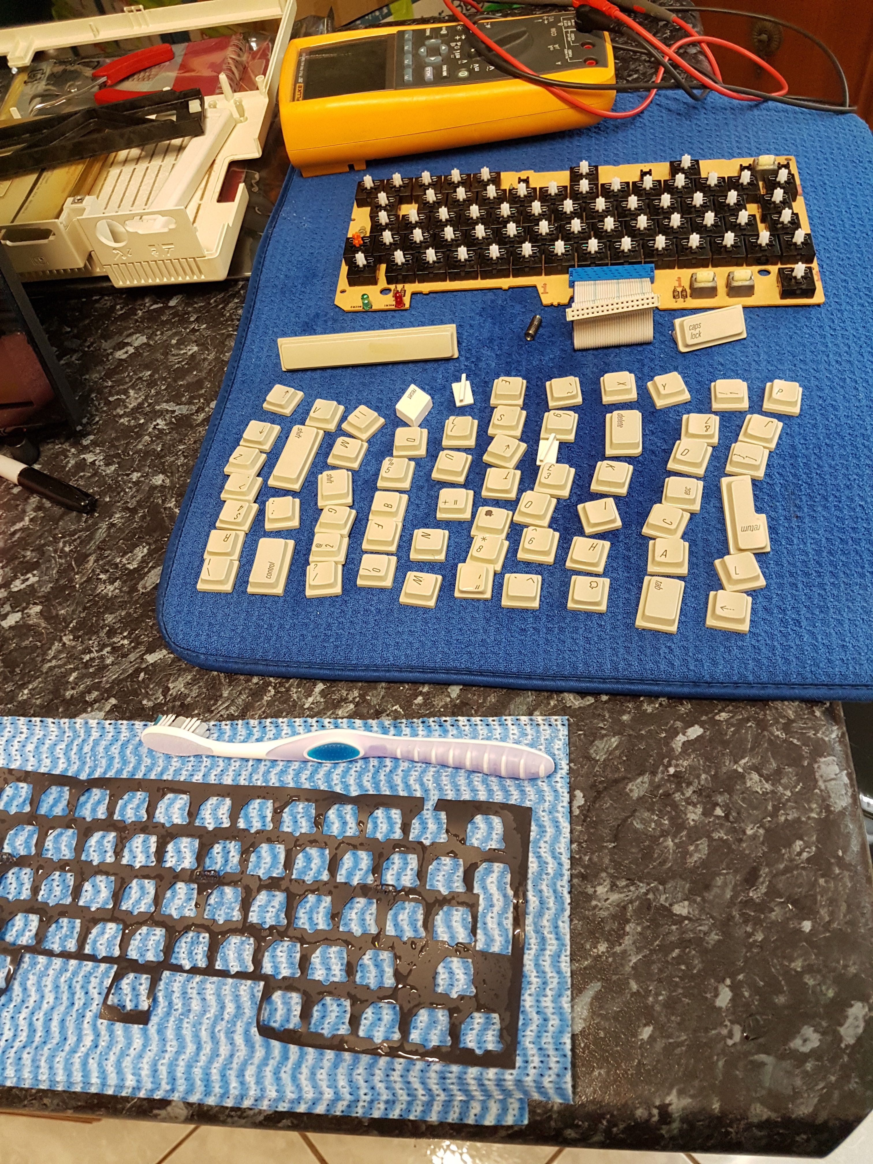
They came up not too bad. Had to let them dry for a while before re-assembling the keyboard. All of the switches work pretty well, and are usable. I may look at trying to replace some, or at least remove, open up and clean out internally. The enter key was a bit sticky, same with the Dvorak and 80 col toggle switches at the top.
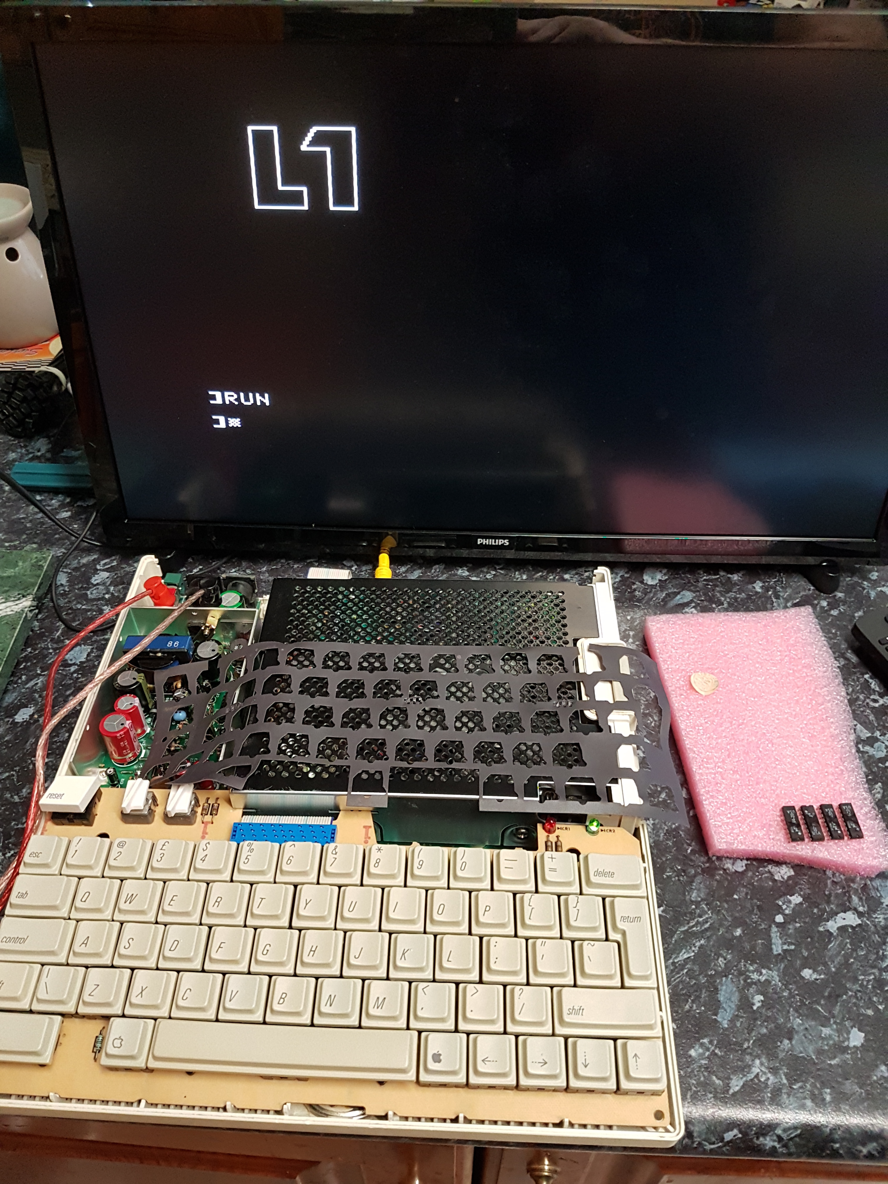
Put all the keys back on and tested by writing a small program. Of course I forgot to put this plastic sheet back under the keys, so will remove them all again at some stage.
Found a source for some floppy disks, out of the states. A pack of 50 should keep me going for a while.
Screen
Looking into the whole video output situation. This information might not be totally accurate, but is my understanding at this moment in time. Apple 2 did some funny stuff to generate colours. Some kind of wizardry from the Wizard of Woz. Pixels are stored 7 at a time in a byte in RAM. The remaining bit specifies which pallet. Odd pixels and even pixels are the different colours for the specified pallet. Two lit next to each other make both white. Not to mention the 64:1 interlacing. This is all without getting into the double high res.
It seems they designed the Apple 2 to output NTSC. It generates the colours by doing some kind of trickery that doesn’t conform well enough to standards. The PAL versions of the computer only output black & white through the composite port. However, this model has an additional video out port, that exposes a bunch of digital lines. Some people have made their own hardware to convert this output to component yCbCr, but that wont work for me. I am thinking I can make my own adapter to output VGA. There were adapters made back in the day to output proper PAL, but they are probably rare as hens teeth now.
VGA sounds complex, but it is pretty easy to understand. You have two sync lines, one vertical for each page refresh, and one horizontal for each line refresh. Then independent RGB lines containing the colour and intensity information. This would be much easier to generate than some kind of component colour space, where they store intensity and colour information separately to cut down on information.
I already have access to line sync pulses, and intensity pulses for each pixel. Might even be page sync pulses, need to wait for my cheap $10 logic analyser to arrive. Once i find the info I need, need to translate the sync pulses to the right levels/polarity/duration, and see what happens!
Maybe a monitor will display it, maybe it wont because it doesn’t conform to a predetermined resolution.
RAM:
My replacement RAM chips, sockets and some other stuff finally come in. I spent some time desoldering all of the current chips and installing IC sockets in their places. This should make it relatively easy to swap chips out in the future.
Although, the sockets I got were really cheap and nasty ones off ebay. They still have clips that contact the IC legs from the inside and outside, just very thin and prone to breaking.

This finally solved the RAM BIT failure. As it turns out, the errors it was reporting was on the aux bank. It seems to test the main bank first, than the aux bank putting the asterix there for any errors. So it was telling my AR5 and AR7, as well as AR0 were bad. You kind of keep replacing the chips until the errors go away, due to the interlaced nature of ram addressing.
The bits came in for the serial cable also. A standard USB-RS232 serial cable. I hacked up a RS232 extension cable, got a 5 pin DIN 180 degree plug and wired it up. Now I can use the amazing ATDPro (http://www.adtpro.com/) to copy disk images from a computer directly to the computer, to a blank disk. This solves the major problem of how does I use it. Once the cable is connected, you sort of redirect the serial input to main PC, and the program takes over writing a small bootloader directly into the computer memory.
I also downloaded and ran an Apple II service disk, and did another RAM, ROM and disk drive test. All checks out.
Next Steps:
- Joystick
Pretty easy to make. I think I have the neccesary parts. The tricky part is getting a dual axis 150k potentiometer joystick. However some clever people (http://quinndunki.com/blondihacks/?p=2225) have looked at the Apple IIc schematics, and figured out you can use any sized potentiometer as long as you add capacitors to balance out the flipflip discharge timing. Yes this was before you had microcontrollers with nice easy to use ADC built in. The apple uses a flipflop, which pulses once triggered. How long it takes to change state back is determined by the axis position. Must be annoying for game programmers, having to burn all that time waiting for the joystick. - Colour Output
Have some bits for this. The model I have is the PAL one, which only outputs black & white on the video port. All colour was generated by messing with NTSC signals anyway, wouldn’t work on PAL. Going to start reproducing the circuit someone designed to output component colours, and work from there (https://kaput.retroarchive.org/appleii/). Trying to output VGA is going to take some grunty processors, or something with enough memory to manage a frame buffer. The timing is super critical on the H and V pulses, porch delays. - New power supply, again.
It seems to draw a bit more than the rated power. Might try and use a beefier one than last time. I have a bunch of old laptop universal supplies lying around. Will probably try and canabalise another one. Also need to find a nice female DIN style plug that won’t immediately fall to bits as soon as I try and use it. I got some cheap ones off eBay, which fall to bits as soon as you try and use them. The plug is a tight fit.