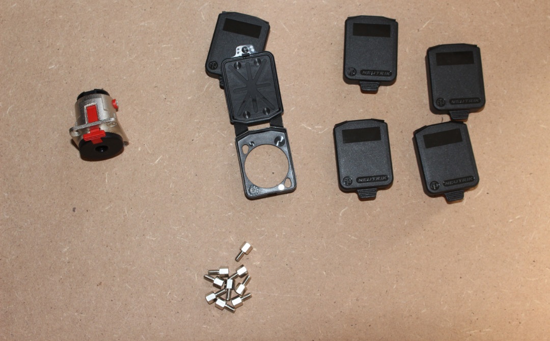
Neutrik Covers for XLR-type throughpanel connectors (as you may notice 6, when in this post there are 7 covers. That is because I got a number mixed up).
Neutrik TRS-Connector with locking tap (yes, metall housing).
And 9 M3 to M3 standoffs.
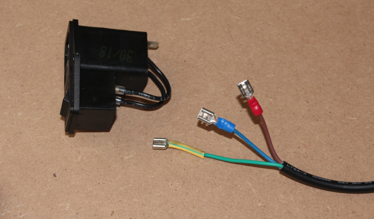
Next thing I got done was the AC distribution. The internal wires are all hooked up in the grey distribution box seen in the pic above, the only thing missing was the step to the socket.
Crimped:
Text-Only Minor Update
Will figure out exact fan and front I/O positions, make a drawing of it and take the DXF and the aluminium sheet to my uni.
Might be able to get a picture of the waterjet in action.
Update
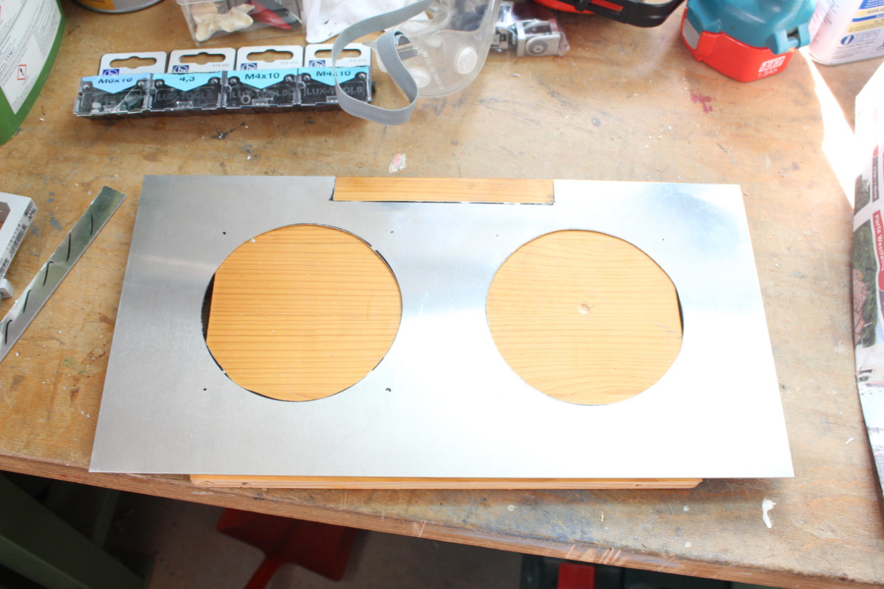
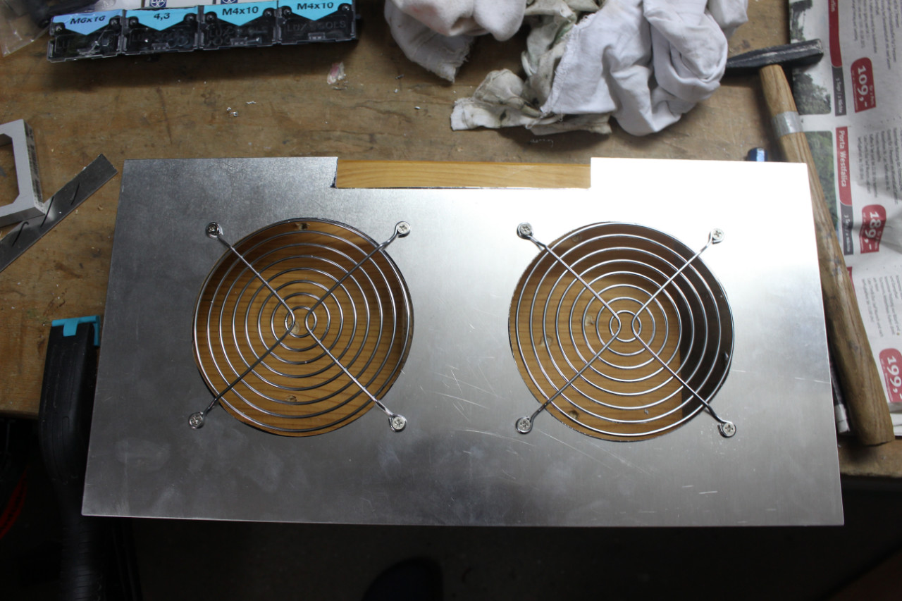
Have to cut the holes by hand. So a lot of saw action, sweat/tears/blood and file work to clean it up again.
Will probably only take pictures of test fits.
Expect declaration of total defeat or victory and completion by friday.
A very pissed off MazeFrame rant
At my uni, there are some things that are good, others that are bad. And one thing that pisses me of on a daily basis.
That thing is when you “test the waters” for a project, basically get the ones who have access to tools to know you and interested in a project it is all “no problem” and “when do you want to start?”
When you then get going, get plans and drawings made, are one step before project kicks into gear, there is a big fat “who are you peasent that you dare speak to me?” Not just once, not just on this project where access to heavy machinery would help, but on EVERY FUCKING OCCASION I or someone tries to get things moving. My uni is a fucking mess that should be embarrassed at their garbage tier internal communication and organization, at least I hope for them that it is that and not them lying about all the “possibilities” they “offer” (as in they don’t) to their students.
I will do it!
I am going to spend money on tools I only need this one time (a hole saw 24mm, maybe a Dremel and a few attachements, maybe a 120mm hole saw).
I got 0 tries, no test pieces, no chance of backup arriving on time.
I either commit and fail or I commit and win (the prefered outcome).
This. Mark the cut lines clearly, and if you are not happy, wipe them of and redo them.
And before you start cutting, try to think the whole process step by step in your head from start to finish before doing anything. It helps a lot when you have a plan in your head and know what you are going to do next.
I got 4 more days to get this done (and dusted. Can’t have aluminium dust blowing through a computer).
Tasks list
36/54 holes drilled
7/10 alu sheets ready for installation
7/10 alu sheets installed
PSU mount
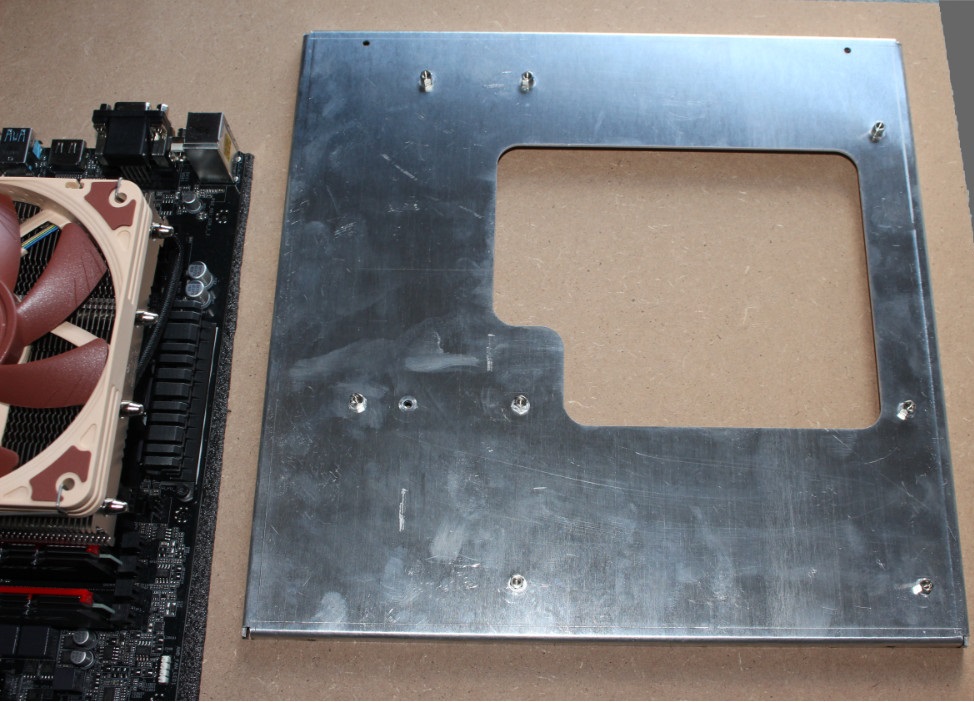
Mount mobo-plate:
0/6 holes drilled in acrylic
Cable management:
Final assembly: in progress
Wow, that’s really cool - I enjoyed reading through your progress. I’m sure you’re already aware, but those extrusions will definitely hold up - we use them to literally build furniture at work (modular, for special events) - like 8’ bar frames that support heavy 1.5"-2" thick mdf/formica tops. The connectors wear over time with stress, but they are cheap/replaceable - and it’s likely you’ll prevent drunk 300lb men from leaning on it anyhow. We just insert acrylic panels/etc in the extrusion grooves as you noted you could have done, but affixing to the outside should give a more finished look. Good show!
Final assembly is in progress.
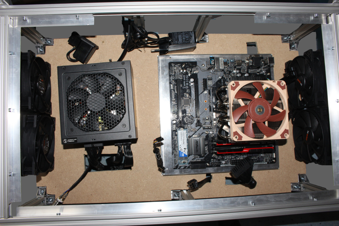
PSU is mounted, mobo plate is mounted (with zip ties, for better or worse). What you see in the following picture, is how I kept the GPU-holder plate from crashing on the mainboard (yes, that is a 32mm socket, has the perfect hight).
Bottom frame complete, GPU in place (need to figure out how to hold it down), monitor PSU in place. Hidden from sight, the powerbutton and fan splitter for the intake fans are hooked up.
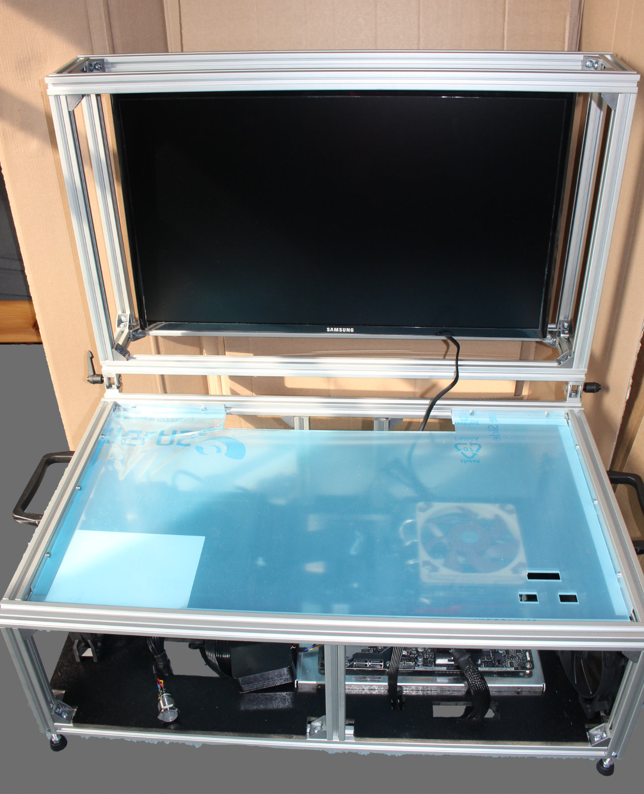
Lid assembly is complete. I may or may not have overlooked the need of the monitor mount to have one screw put it. Why that is a problem?
Because to take out the monitor, I need to remove no less than 17 screws.
A simple fix would be to drill one 10mm hole, problem is that I need to remove 16 screws to do that…