I am planning my first custom loop. I am almost ready to build, just waiting on few more fittings that I didn’t realize I needed so I had to order more. I am trying to plan out the loop by looking at other builds on reddit and Instagram. My question is why does it look like some people use all 4 ports on the gpu block going from gpu to cpu and then back to gpu. I’m assuming people do this just to show off more tubing and fittings or make it look the way they want it to. Does it affect the flow at all? Or how does that even work? In my head it seems like that would mess up the flow through the gpu block since you’re going in twice and out twice. It just doesn’t make sense to me how that works. I think It could look nice having 2 parallel lines going to and from the cpu and gpu instead of just one line up to cpu and then line out to the radiator. If these details matter at all I am building in the o11 mini. I have a 240mm radiator up on the right side of the board towards the front of the case and a 360mm radiator across the bottom of the case, with d5 ek classic 160 pump/res combo mounted on top of that 360mm rad near the front of the case. So I was planning on running lines from pump out to 360 rad, then to gpu, to cpu, to 240 rad, back to pump/res.
No it doesn’t work that way. If you put the CPU and GPU in a single loop (which is what most people do) your 360 rad is probably enough.
if you plan on overclocking either or both CPU&GPU, you probably need a split rad config and apparently, you have the parts for that. It relies on 2 T-junctions in your lines: one on the output of the pump, the other on the input of the reservoir. The output of the res is connected to the input of the pump. From each T-junction, the line goes to the CPU or GPU and their respective rads. Mind, this is fairly hard-core OC/water cooling stuff!
One more thing: make sure the pump is always the lowest point in the loop. Your parts will thank you for it  (by living longer!)
I was just confused by pictures of builds that look like they use all 4 ports of the gpu block. I was just trying to find a picture of one that was set up like this but now I’m having a hard time finding one so maybe I was just confused by someone’s more complicated loop.
I have a 3950x with a per ccx overclock of 44, 44, 42.5, and 42.5 on ccx 0, 1, 2, and 3 respectively at 1.275V. I have used this OC with a 360mm AIO for over a year and I imagine I’ll keep that OC the same once this is set up. I havent had any luck getting clocks higher than that without increasing the voltage and I feel like what I’ve got at 1.275V seems like a pretty good sweet spot for me. What I’m really excited about is I finally got a 6900XT and I’ll be ditching the ugly red accented reference cooler and swapping in a waterblock from alphacool.
The pump/res can’t quite sit at the lowest part of my loop because the 360mm radiator spans the entire bottom of the o11 mini case, so it will sit on top of that but it will have a 240mm radiator above it with the 240mm ports at the top of the case. My loop order will be pump out t-split between drain port and 360mm rad in, 360mm rad out to gpu block, gpu out to cpu in, cpu out to 240mm in at the top of the case, then 240mm rad out to res/pump combo.
As long as you have a reservoir before the pump (if they are separate) you should be fine. Order itself is really not that important and wont see a huge difference in temperature (unless 1-3C is a big issue for you). I have had bottom rads like your saying you will have. You will probably have to “tilt” reorient it a few times while your filling, or while your doing a 24 hour leak test, but with a sufficient pump the bubbles and air pockets should make their way out of the system. I usually go, Pump/res to rads to cpu to gpu (or vice versa) depending on the run. Thermally the water is moving fast enough the heat load should be dissipated equally and stabilize no matter the order. I hope this helps. I’m happy to help if you need more assistance. A Image would help as well if you have one.
Heres a example I have with split rads and a soft tube build from the past…

The tube tucked in at the top is a fill because I was leak testing, and the lower tube was my drain line.
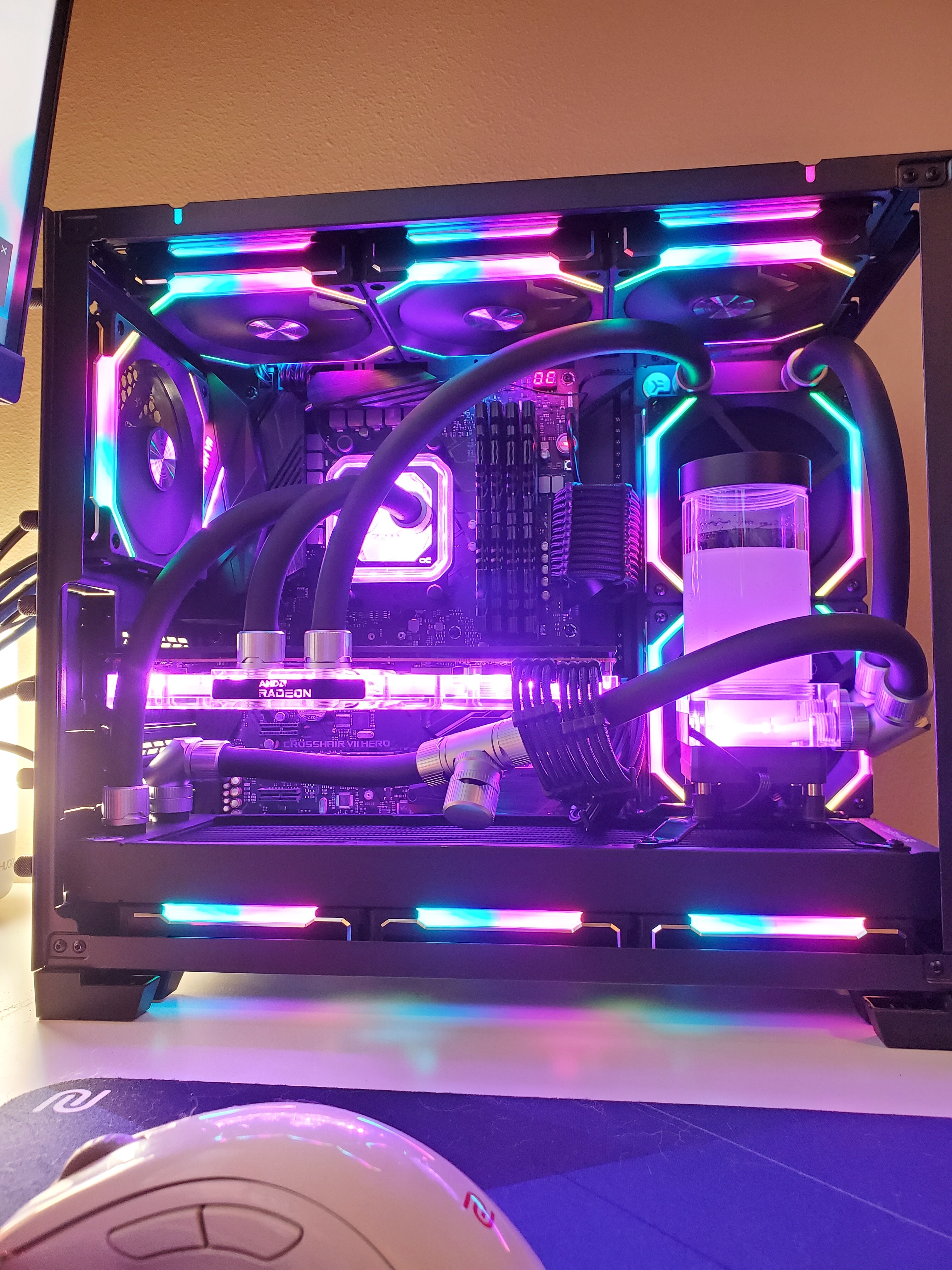
I finally got the fans I was waiting on to ship from China and put this build together. I want to clean up that front line with the T fitting, but I was having trouble fitting that drain valve closer to the ports and I was anxious to get it turn on to make sure everything was working. I used more power tool to draw 350W with the 6900XT and my graphics score was 20,800 in Timespy. I am 1.02% off of the world’s best for my 3950X / 6900XT hardware configuration.
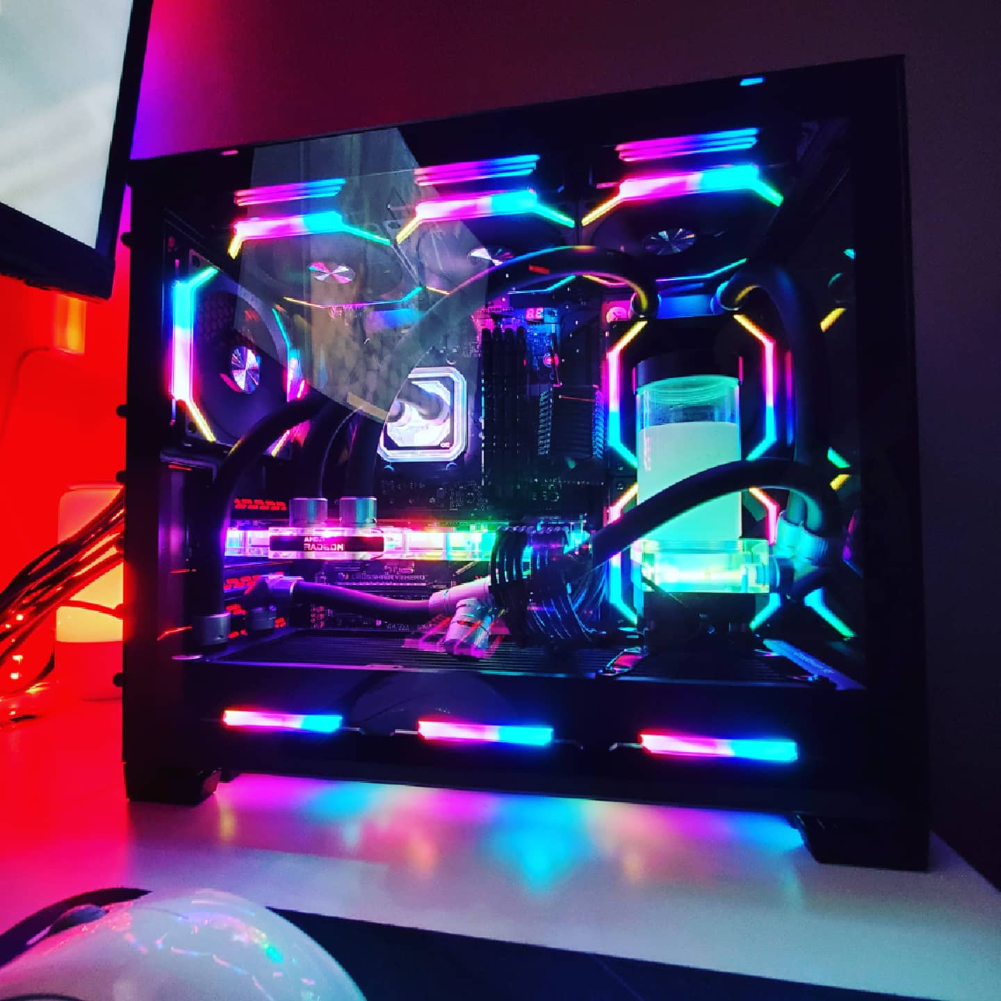
Here’s an image with the glass removed. Could take better pictures but it was late when I finished and I was more focused on getting some benchmarks run.
Very nice, hope its keeping things nice and cool for ya!
Too much rainbow puke for me but it’s nice. ZMT always looks awesome.
having reservoir feed pump is the important part, other then that you can have rad gpu rad cpu and overclock both, but make sure rads can handle the load.
This topic was automatically closed 273 days after the last reply. New replies are no longer allowed.