Photogrammetry experiments using focus stacking

During my Devember project I did a quick experiment with extracting depth information using focus stacking:
http://other.spillerrec.dk/3d-depth-test/

which somewhat worked. Later I had the option to automate the focus bracketing required to automate the process, so I could easily take 50 images instead of the 17 I used before. With a bit of an opdate with my detph estimation I got this:
http://other.spillerrec.dk/3d-depth-test2/

I now wonder if I could use this to make a simple photogrammetry application, that is making 3D scans of real world objects. Since I have depth information, this should be a lot easier. (I did try using existing software, but it they were complicated and I couldn’t get any usuable result out of them. So I think it will be more rewarding trying to implement something myself.)

I have tried taking two shots now:
http://other.spillerrec.dk/3d-depth-test-dual/


So next step will be trying to combine these two. I will start by just manually specifying a few points and see if I can align them that way, otherwise I think OpenCV has something I could use here.

7 Likes

I tried making a UI with Javascript to create a set of points where the images matches up:


I’m not very experienced with JavaScript, but it seemed like the easiet solution and it certainly was very straight forward. (Change the window size and everything breaks though.)

I tried to rotate and translate the two depth images to match them up, but it became very clear that I forgot something important. The perspective is different and I will need to correct that as well.
However I don’t really understand perspective that well. I have tried to do perspective drawing and use those 3 points to simulate the effect in the past, but I don’t understand the “why”. How does those 3 points change when you change the camera angle?
I could pick some lines in these images which I know should be parallel and straighten up the image that way. However how could I know that they really are parallel if I hadn’t seen it in real life? And what if there are no straight lines in the image in the first place? I want something better than this.

So next order of action is to get a deeper understanding of perspective and the math to revert it.
After that I will need some regression analysis to match them up somehow, which I probably also want to dig a bit deeper into the theory behind even though I could probably get it done without. I will probably use Python for that part, though I will probably want to port that to C++ at some point so I can incorporate it with the code that is doing the depth estimation.

VR

I was looking into VR in the browser to see if there was a way to visualize this in VR. The experience is a bit wonky, but VR in the browser actually works. (Browsers are basically a hacked together OS by this point, what has the world become?)

I managed to find an existing project which should be able to do what I want:

https://modelviewer.dev/

It is a 3D viewer to embed into websites and it supports WebXR. glTF is a new 3D model format intended to be a interchangeable 3D format, and it should be as easy as just loading that file into the webpage. Blender can export to it, so all I need to make a OBJ file I can load into Blender. So I have done that now.

Of course it would be easier if Blender just supported VR in the first place. And of course it does:

https://wiki.blender.org/wiki/Reference/Release_Notes/2.83/Virtual_Reality

There is no interface to move the camera, but it looks better than what I saw with WebXR and you can still move stuff in the normal interface using the keyboard for now.

In VR, the perspective distortion is definitely more visible, so this should help me with getting this corrected properly. The glib file (binary version of glTF) exported from Blender is larger than the text WaveFront OBJ I imported at almost 700 MB which is unreasonable to actually share on the Web. There must be something wrong with that file size, it just can’t be right.

Perspective

With the perspective deformation, I believe I get it now and it should be a lot simpler than I thought. Basically the three points you see in perspective drawing are the points where parallel lines in a cube meets at infinity and is a side effect of the perspective projection. A slightly rotated cube would have 3 different points and they are directly related to the angle to the view point.

All I need to know to correct the perspective is the distance to the camera and the field of view.

I asked one of my colleagues if it was possible to translate the distance from the camera using the lens focus position and apparently there is a profile for that. So I will have to look into that. One thing I already noticed however is that this goes to infinity at the end of the focus distance, so the depth is non-linear and that might have a noticeable effect on the transformation.

The next part of it is the field of view which I think is defined by the zoom level. I’m not completely sure how it works, but I should be able to figure something out.

Next steps

  • Extract the focus position from the exported images. I saw the information in the meta-data in PhotoShop, so that shouldn’t be too difficult.

  • Find the lens data for the zoom lens I used and translate those focus positions to real world distances

  • Figure out how the field of view is defined for a lens

  • Correct the perspective, preferably using the information of the lens, otherwise try to figure out some settings which looks decent.

4 Likes

Field of view

This was surprisingly simple. The focal length (the “mm” distance specified on the lens) defines the field of view. The focal length is the distance from the sensor where the light converges to a single point and thus defines how much it needs to bend the light rays to cover the entire camera sensor. So if you know the size of the camera sensor, you can calculate the FOV like this with some simple trigonometry:

2 * atan( (d/2) / f )

where d is the length of the diagonal of the image sensor, and f is the focal length of the lens. So with the 54.7 mm sensor at a focal length of 35 mm you have:

2 * atan( (54.7/2) / 35 ) = 76 deg

Distance calculation

The profile contains 14 values, with one of those being infinity. So I tried to make a function to smoothly interpolate these:
image
Excel could not find trend line which could fit those points properly. But maybe this was a hyperbole on the form 1 / x? Reversing the points (as they were defined originally) and multiplying with x gives a nice linear curve:
image
Then all you have to do is to divide by x again and I now have a perfect fit:

There is one issue however. This is a zoom lens and the distance appears only to be defined for 35 mm, and it is clear when using the camera that the nearest focus point changes when you change the zoom, so these distances must change when you change the zoom. Maybe it can be defined from the change in FOV? I will have to see if I can get in contact with someone from my workplace that knows…

Extracting the focus position

And the first major disappointment, I had misunderstood what the EXIF data meant. When I saw the 355/1000 number I through this was the focus position out of 1000 steps. Nope, that was a fraction specifying the distance in meters, and of course this has a resolution of 14 steps, exactly the same in the profile I received before.
Since I used the automatic focus bracketing feature to take 50 photos, I know the focus distance should have been increased with the same amount each time. Using the EXIF data and the profile, I found the original steps and tried to interpolate them:


I feel like it is probably rounding down, but I have no way to check as those 14 focus positions are what the camera is writing in the RAW file. I’m sure the internal resolution must be much higher though.
All there is left is to calculate the distance for my 50 images:

It is clear that this non-linearity mainly matters for objects far away.

Correcting the perspective

So now, in theory all I need to do is to center the image on 0x0 and scale the x and y positions with atan(fov) * distance. And that works:


Left is the orthographic projection which appears to look quite a bit better (but not perfect) and right is the perspective projection using the same FOV. The perspective correction clearly shows that I have calculated the correction correctly, as it is countered perfectly.

I don’t think it is quite right however and I think it might be the distance. Next step is to update the script I use for importing it into Blender so I can better check out what is happening, and if it looks good, try to overlay both angles on top on each other and see if they matches.

3 Likes

not sure if you need more learning resources, but I saw two minute papers cover 3d photos, which seems similar to your project.

1 Like

Thanks for the links, I had seen some of them though.
Some of those models just interpolates small changes of viewing angle, and that is not what I’m looking for. I would like to build build a proper 3D model by using images from different angles. So the ML models which estimates a depth map like the ones I made are more interesting.
I have been thinking of trying to use machine learning to improve the depth results I’m getting (I do have experience with it), but I think the results I’m getting so far are good enough to verify if this is going to work. It can be done without depth maps, but I was hoping that it would simplify it a lot. I do think depth maps will eventually be solved with depth cameras, getting such a camera is still just too damn expensive right now.

Update:
Imported it into blender and tried to use the ruler:


It actually looks fairly straight, the distances here are supposed to be 0.18m and 0.23m, so the scale is slightly off. I will need to do some proper experiments to see if the distances of the profile are actually accurate and perhaps some tests to verify the field of view.

2 Likes

I tried updating the camera and lens firmware, as this update now adds a distance meter on the camera. And these numbers were quite different from the profile I saw…
So I brought out a measuring tape, and looked which part of the image was in focus as I changed the current focus. The distances from the camera looked pretty correct, and the ones from the profile was offset by about 15 cm. It is hard to tell how precise it is this way though.

Someone from work reminded me that there is a datasheet for the lenses and this was rather interesting. It shows this lens as having a minimum focusing distance of 0.42m to the image sensor and that the correct panorama center point is 12 cm in front of the sensor.
The profile being offset about 10-15 cm does mean my distances should be relatively close to that panorama center point, and those distances is actually what I need. So my calculated distances in the image should in theory be somewhat correct, certainly not 30 % off.

Double checking everything, I found that I accidentally wrote atan where I had meant to use tan. And by total coincidence, this happened to give a result which was fairly close… Fixing this caused my distances to match fairly close (something like 0.178m and 0.227m, within the margin of error).

My previous images were taken at different focal lengths and the profile only works for 35mm, so I took some new images at 5 different angles, all at 35mm. After fixing a depth issue as well, overlapping those in blender actually works. Here are two of them, taken nearly at 90deg from each other:

It is not a perfect match, they are slightly off, but this is pretty good and certainly shows I’m on the right track. The question now is if this can be used to perfectly align the images by finding more precise values of FOV and depth, if I need to include more stuff in the transformation equation, or if I need to be able to correct small differences locally to deal with distortions I can’t define mathematically.
There are still some minor stuff I could improve, for example the data sheet says that the lens is actually 35.9 to 73.1 mm instead of the 35 to 75 mm which is actually shows both on the lens and the meta data. So my FOV is slightly off.

Another issue I noticed is that how light is reflected at certain angles causes some parts of the images to differ in brightness. Not too sure what I want to do about that.

Next steps

  • Improve the quality of the depth maps. They are a bit too noisy to get a good feel of how well it aligns. I need to improve the filtering, and perhaps I could try to do some AI for getting better focus estimations as well.
  • Get started with some automatic alignment based on those manually specified points. I need to get a feel on how this works and how I can estimate a better value for FOV, etc. using it. I will probably start with just aligning the rotation, and then slowly add stuff to it.

Not sure which of the two I want to start on first…

2 Likes

I decided to do some work on this again after forgetting about it for about 3 months. Not really sure why, I think I was busy with work for a while and then stopped thinking about it.

But I made some progress this weekend and that is the important part.

Focus detection in Bayer

The depth estimation is based on a Laplace edge kernel using the fact that blurry areas also means softer edges, so areas which are in focus will give a larger response. So making sure the edge detection is as good as possible should improve the results.

So the question is, what is the best way of doing this? Should it be done on each color channel separately or done by calculating the luminance and doing it on that? ETC. The open-source program for focus stacking does the luminance approach and then does some extra gradient checks in attempt to fight bokeh issues fake edges appearing in out-of-focus shots next to the real edge.

I was thinking that this might be caused by the color channels going out of focus differently. Lenses causes issues with color channels, such as chromatic aberration causing colors to be shifted depending on the angle to the center of the sensor. Similarly, how out-of-focus areas are can be different for red, green, and blue. So the right approach to fight this issue might be to work with red/green/blue separately.

The problem here is that demosaicing correlates the color channels and combines them in a non-reversible way and then color correction later mixes them up in a way unknown to you. So when you get the image out of your RAW processor, there is no way to get the original red/green/blue channels. So that means skipping the RAW processor and working directly on the RAW bayer data.

Oh my, look at that noise…

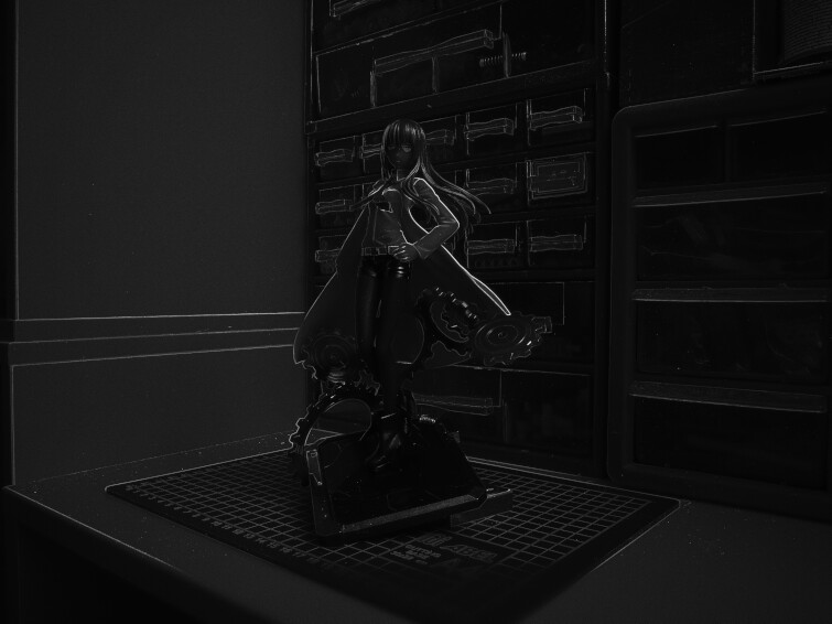
I used libraw to get the RAW data from the images and converted the bayer pattern into a four channel RGGB image. Then I performed the edge detection on just one of the green channels, which gave this result (the maximum response of all 31 images in the focus stack):


An edge detector should give black for flat areas but there large areas which are obviously brighter. These happen to be bright areas in the image and I remember the DNG RAW file format specifying a noise profile where:

noise = sqrt( pixel_value * scale + offset )

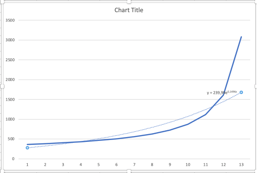
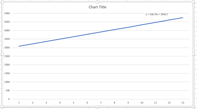
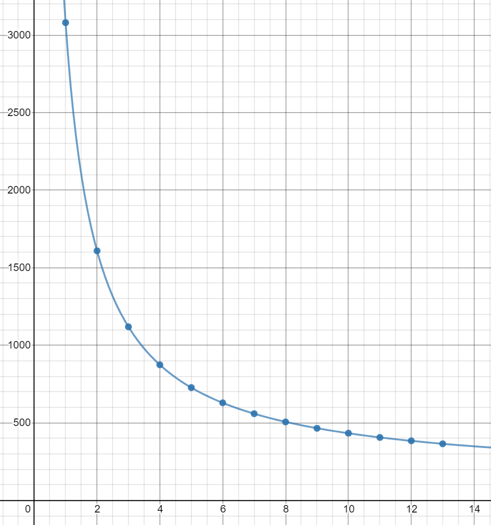
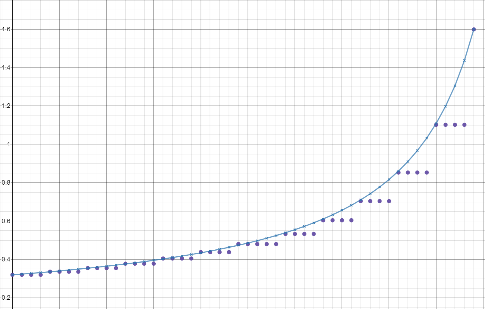
meaning that brighter areas in the image contains more noise. Going by this idea, I made a histogram of the response of the edge detection compared to the pixel value:


If we look at the first half, it follows such a square root functions quite nicely, which I plotted in black. (The offset could probably make it closer at the very beginning, but I didn’t bother.) The second half of the curve goes more crazy, but that must be the image content affecting the results, as you can see it the same response earlier in the red and blue channels. The red and blue channels are usually less sensitive and needs to be scaled to match the green channel, but you can see they follow the same noise curve before scaling.
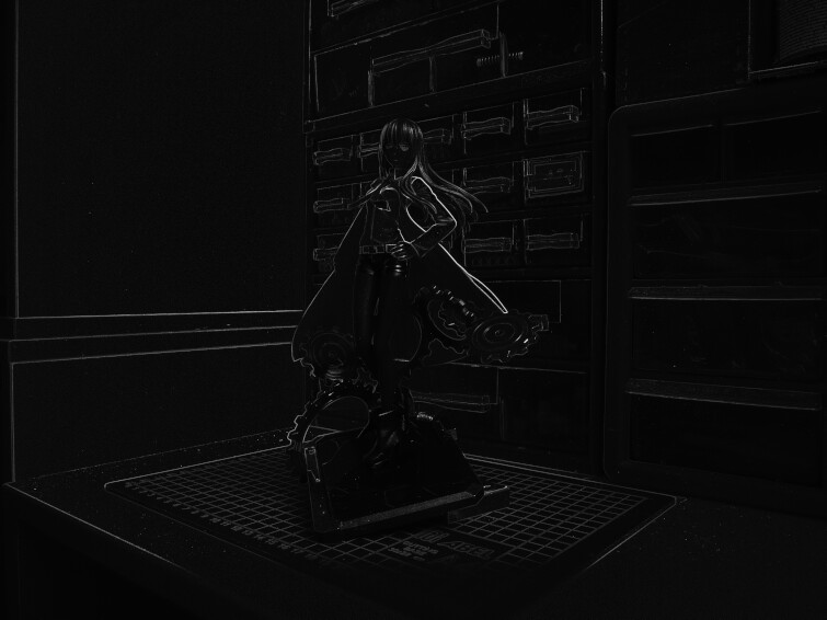
Subtracting this noise level from the image fixes the issue:

This is still not quite perfect, as this just substracts the mean value, so bright areas are still more noisy. There are also some hot-pixels as well, which was normally removed by the RAW processor.

Did it get better

Not really, at the very least not by a significant amount. The edges does appear to be thinner and less blurry, but I will need to investigate closer to see if the “color channels getting mixed” actually caused issues here. I think this approach might be better, but it is clear that this isn’t what is needed to improve the result at the current time.
I also noticed that the image appear to be distorting slightly in the out-of-focus sections. If you compare a shot where the focus is before the subject and one where the focus is behind, the image appear to move. The current focus position might be affecting the FOV or something, which could also be the reason for these “fake edges”, and it certainly will matter for the alignment of multiple images.

Better filtering

One thing that caught my eye was that these large flat areas with seemingly no information seem to somewhat work. It is very noisy, but the results tend to bias towards the right result anyway.


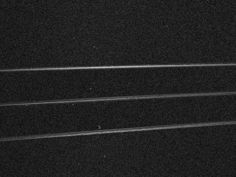
Here you can see the 3 edges being in focus, but the flat area is just one big noisy mess. But I tried downscaling the image, and this suddenly looks more interesting:

The area you see in the top image is on the left part of the image, where you can see the three lines being in focus. And it is a bit difficult to tell, but you might be able to see in this downscaled image that there is a lightly brighter vertical line around that spot.

Seeing this, I tried to make a pyramid based approach where I keep downscaling by 2 and then walks up from the lower resolution, adding the more detailed information from the higher resolution, but using the lower resolution if it seems unreliable.
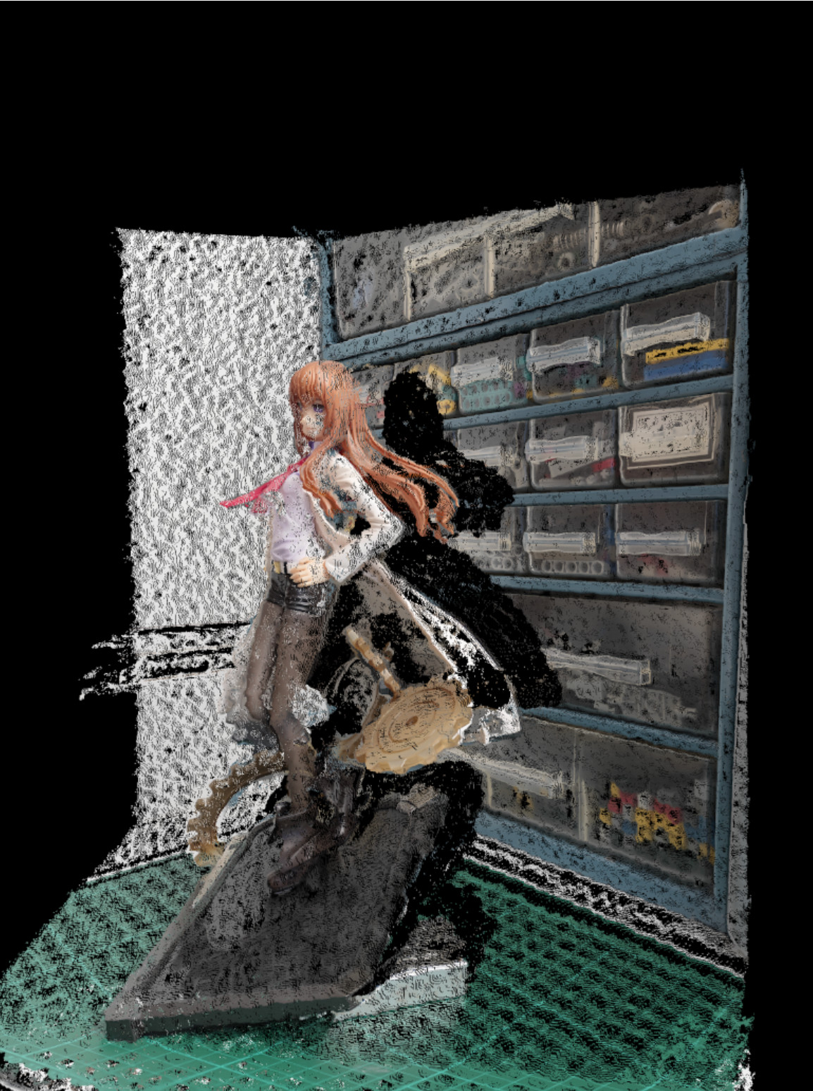
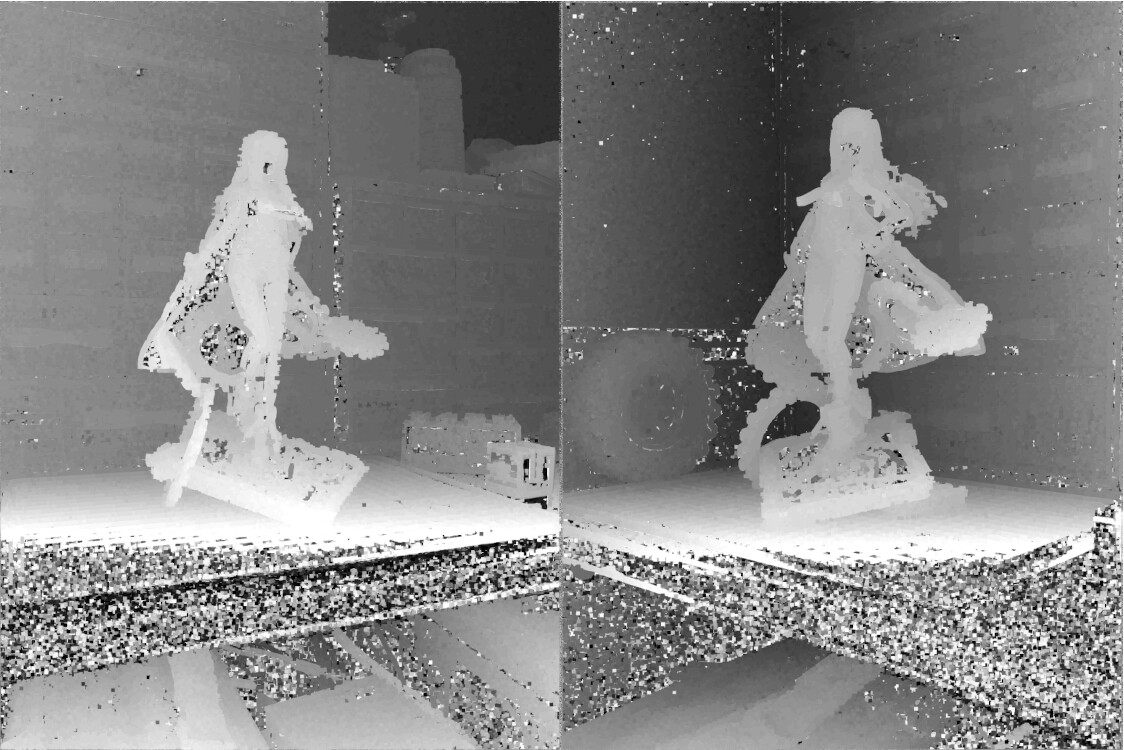
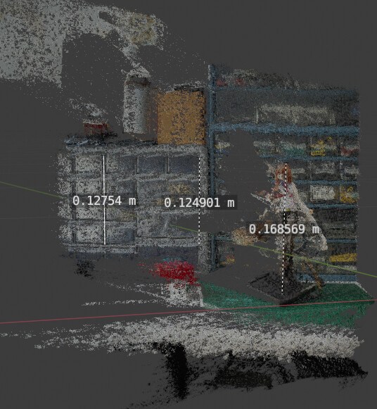
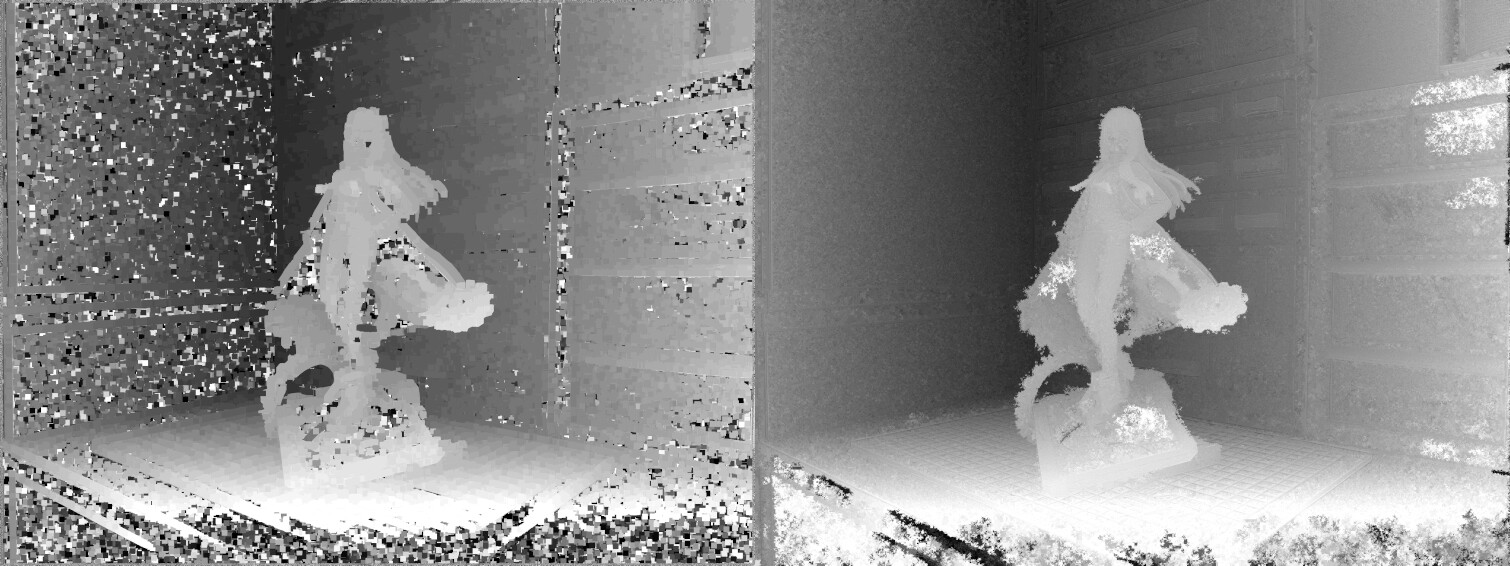
And this gave some promising depth maps:


Left is the old result and to the right is the new result. It is still noisy, but it is much more fine grained and detailed so I can filter it and still have more detail after the fact. There is some other issues though, small areas where you can peak through (such as the gears in the figure) can end up disappearing if I downscale too much, but if I don’t downscale enough noisy areas appear (the bright white spots in this image). And then there are some clear lines in the image where there are edges in the original image, which isn’t correct. So there is still work to be done here, but this looks promising.

Going forward

I will probably look some more on the filtering, to see how much I can improve it. Seeing I just took a 3 months break though, I’m not too sure how much focus I will have on this project, but I hope to get more done on it at least.

4 Likes

This is really interesting, so I’ve bookmarked it (as i don’t have time tonight to really go through it all).

Hey there, I was considering getting started on a similar project to improve accuracy for mesh reconstruction from regular photogrammetry (basically establish a baseline of known good values for specific areas of the model and default to a less precise but more accurate value beyond a certain margin of error). Just reading through I noticed your issue with lighting changing due to direction. It shouldn’t really have any impact on the quality of your point cloud since depth is calculated form a single perspective at a time, but you can mitigate the issue using cross-polarization. Place a polarizing sheet on top of your light source, and another shifted 90 degrees on your lens. This will eliminate nearly all specular highlights and your photo will only show diffuse light, which should stay consistent regardless of the angle. At the very least it’ll help you determine whether these inconsistencies have an impact on the end result.

1 Like