This is the third time I have had to rebuild the LEGO PC (due to moving between university and home) and I decided that I would write a build log for it. This is the second computer I ever built and the first i built for myself. My goal for this build was to make something unique and to see how hard I can push myself as a relatively new builder.
I always loved the heavily modified and scratch built cases that would pop up on various forums but the problem was I didn't have the money to buy a set of tools or the knowledge to use them effectively. After a few months of searching around for a case I liked I stumbled upon someone who had used LEGO as a case material. In all honesty I did not like the aesthetic of it; all the bricks used were of different color and shape which made the whole thing impressive but ugly. (Aesthetic taste is a subjective thing). However it did get me thinking: LEGO has almost no limits, I can do whatever I want with it, it is in essence the ultimate modding tool for whatever you do. After mucking around in LEGO Digital Designer and sourcing the bricks I got to work. Now onto the build:
(quick note: From here on in I will refer to the flat pieces as "plates" and the bricks as... well... "bricks". dimensions will be referring to the nibs on the bricks. ex: 2x2 brick is your standard square LEGO brick)
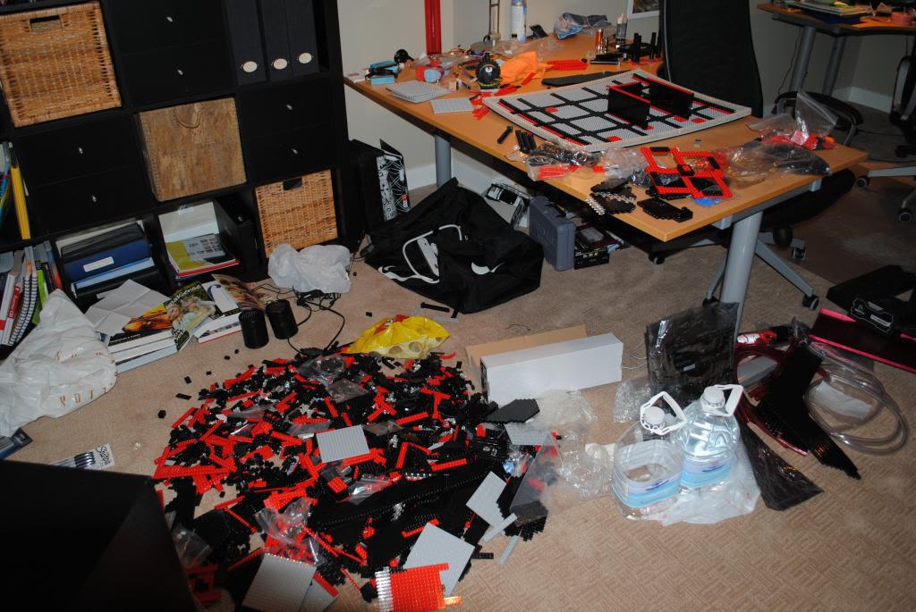
My study area was a disaster throughout this build, many thanks to my girlfriend and housemates for putting up with it.
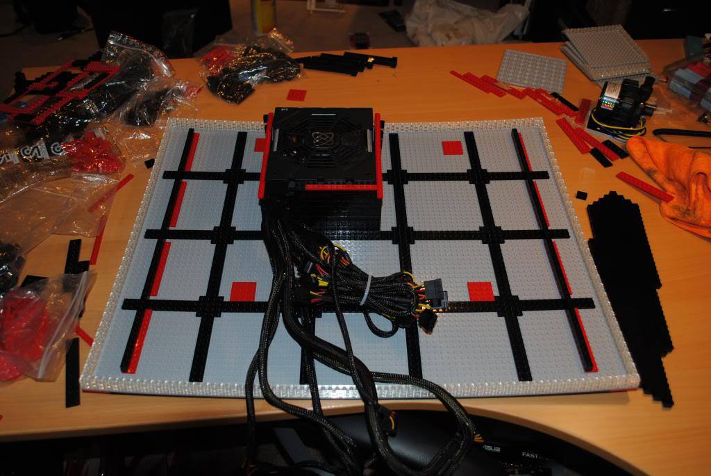
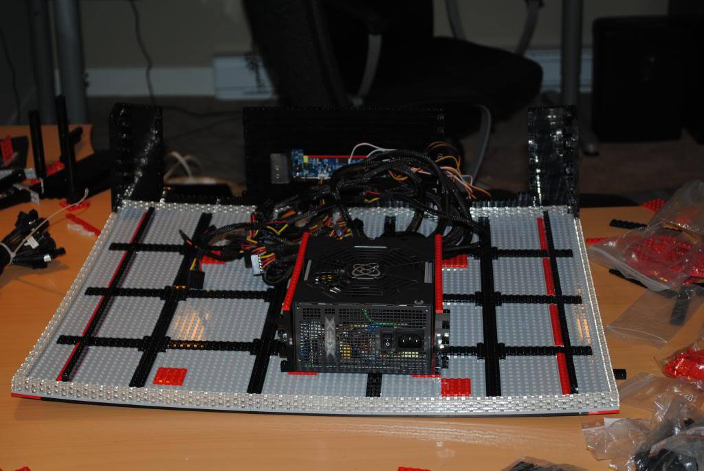
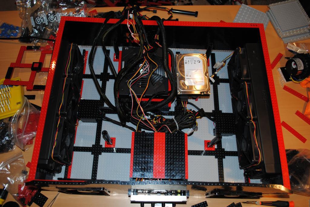
Here we can see the base of the build made up mostly from 16x16 plates held together by 2x12 and 4x4 black plates on top and bottom. All of the red plates shown here are support plates that are mirrored on the underside so all the weight will be supported by the desk underneath.

If you look closely you can see the whole base curve upward at the corners. This is due to the way LEGO bricks are made and is caused by all the clear 1x2 plates that line the edge of the base. The curve disappears as I add more weight. Also the reason the red plates with black bricks on them on the far left and right aren't exactly mirrored is because the 2 radiators I am using have slightly different thicknesses.
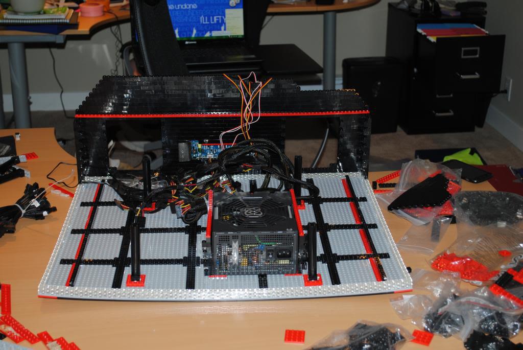
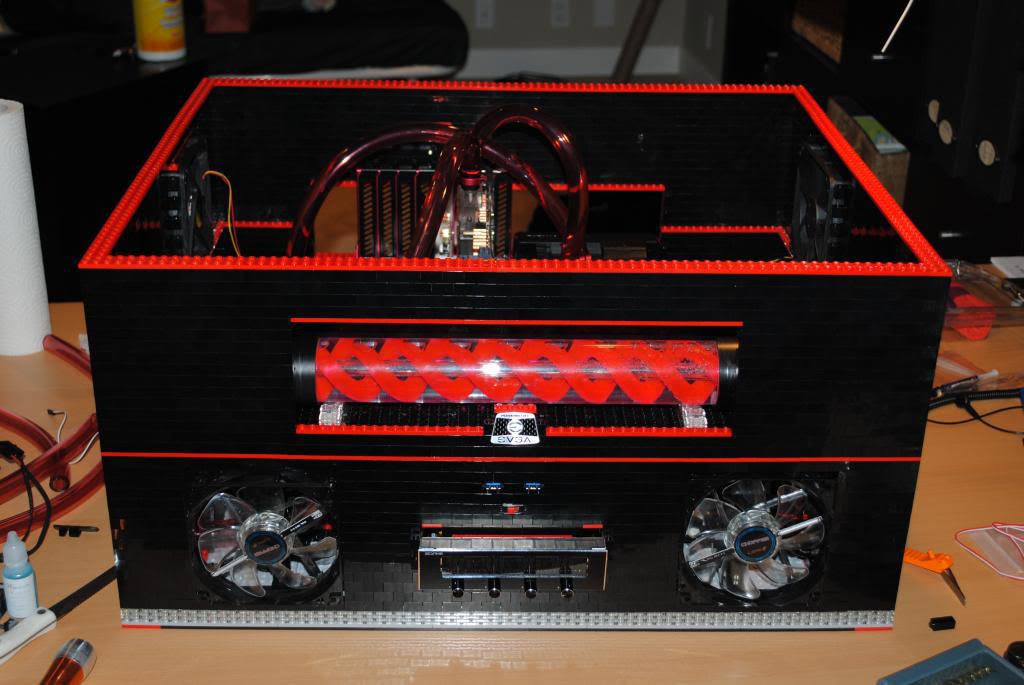
Got started on the front which includes a fan controller and 2 holes for aesthetic type fans (LEPA choppers) All the walls are made out of 1x2 black bricks. That's a LOT of small bricks
View from the back. Here you can see how I had to bend the mounting points on the fan controller to get it to fit snug. The modified fit is surprisingly rigid and needs quite a lot of force to move the fan controller around. First major hurdle taken care of.
The red 2x12 plates that bisect the wall here serve 3 purposes. 1: aesthetics (I love black with red trim) 2: potential mounting support (the 1 nib thick line that sticks out I use for highly customizable support) 3: Wall rigidity (having so many small bricks all connected together causes the wall to bulge due the small tolerances between each brick being effectively multiplied. With this many bricks I could literally do an S bend without the plates for support.)
I continue building the wall and make room for the first radiator. Here you can also see the four pillars that will hold up the motherboard. The one and only time I used adhesive can be seen here as the epoxy that joins the connection between red support plate and black pillar.(due to the price of the components it holds.)

A problem I came across in my previous versions of the LEGO PC is the hole to connect the PSU power cord and reach the switch was too small for human hands. I have learned my lesson here.
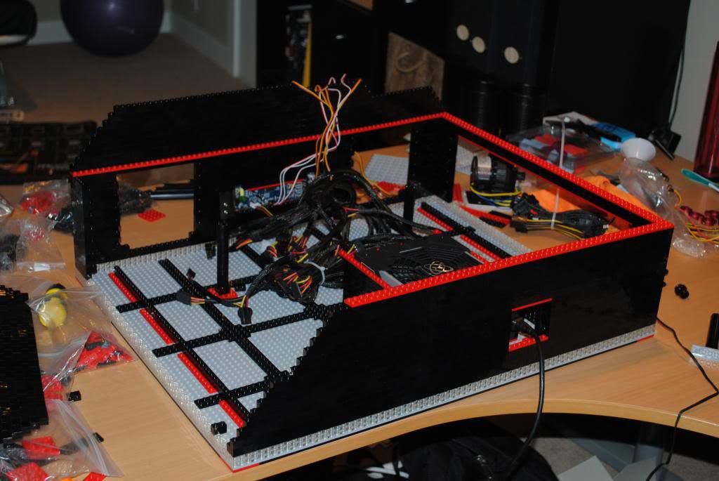
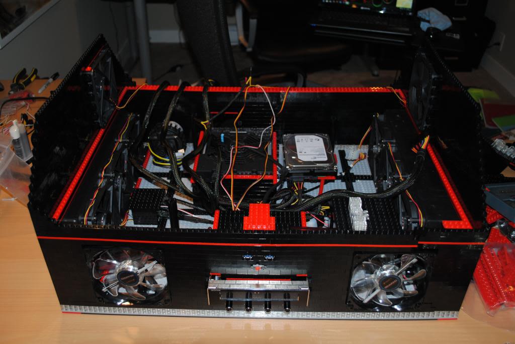
The lower half is all done. Its finally starting to look like something.

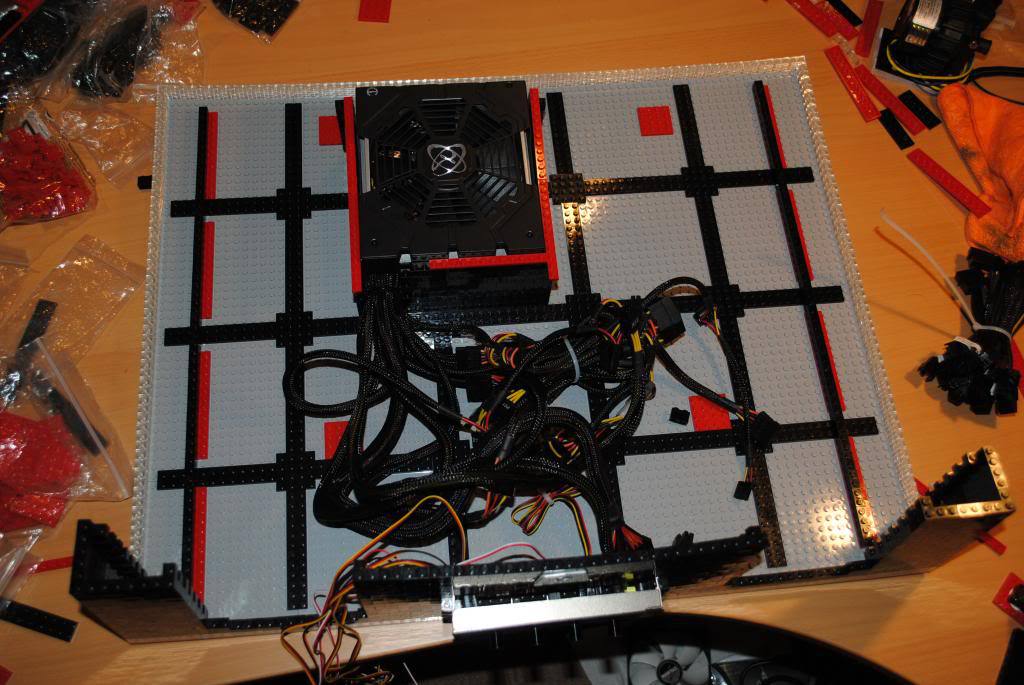
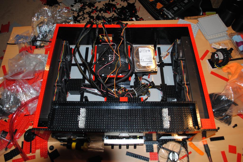
I have installed the radiators with their fans. The small black boxes right next to the radiators house all but one of the fan wiring and connections. Cable management is so easy with LEGO if you have the patience. Also seen here is the all red platform that will hold the hard drive.
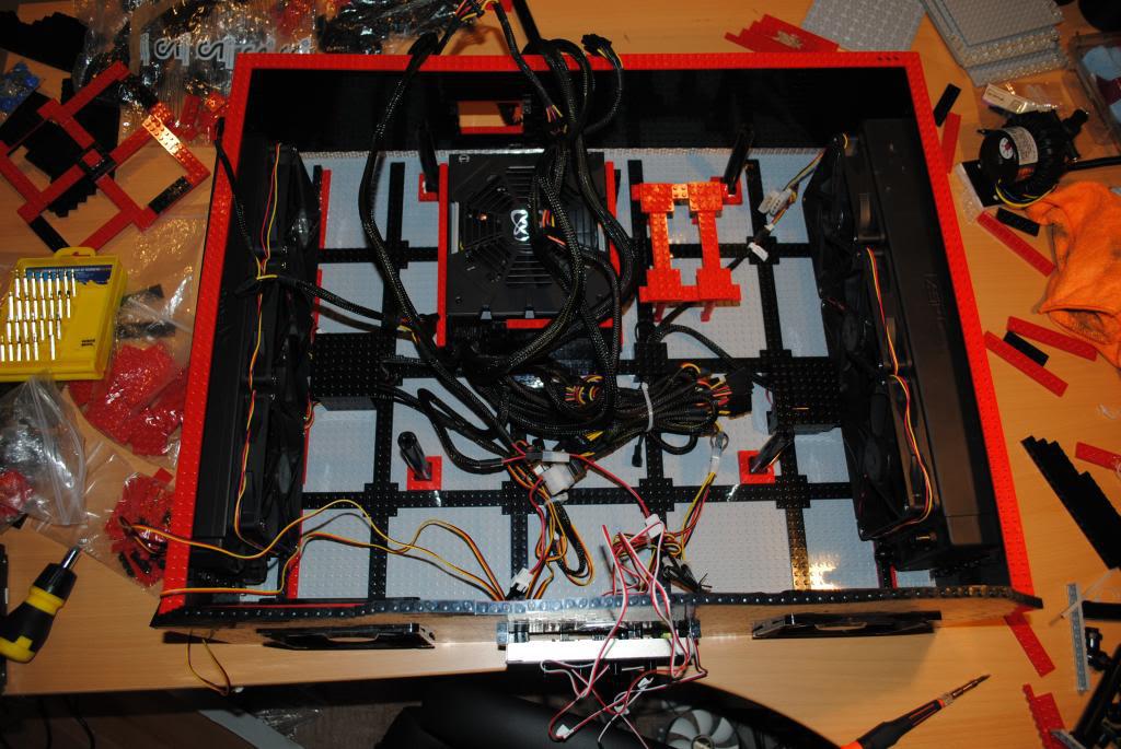
More cable management and the hard drive with foam padding underneath to stop vibrations.
Here you can see what I had originally planned for the reservoir. However I tore down the whole front after this picture due to some connectivity changes I wanted to make.
After receiving a CCFL kit in the mail I decided to make some changes. I put the switch for all the lighting on the front wall and tore apart a front panel USB 3.0 connector for some easy access USB love. You can't see it too well in this picture but I made a brace out of LEGO that is built on top of the wire management box. This supports the switch and USB ports and keeps them from falling inwards when I use them. Don't worry the EVGA badge will be back.
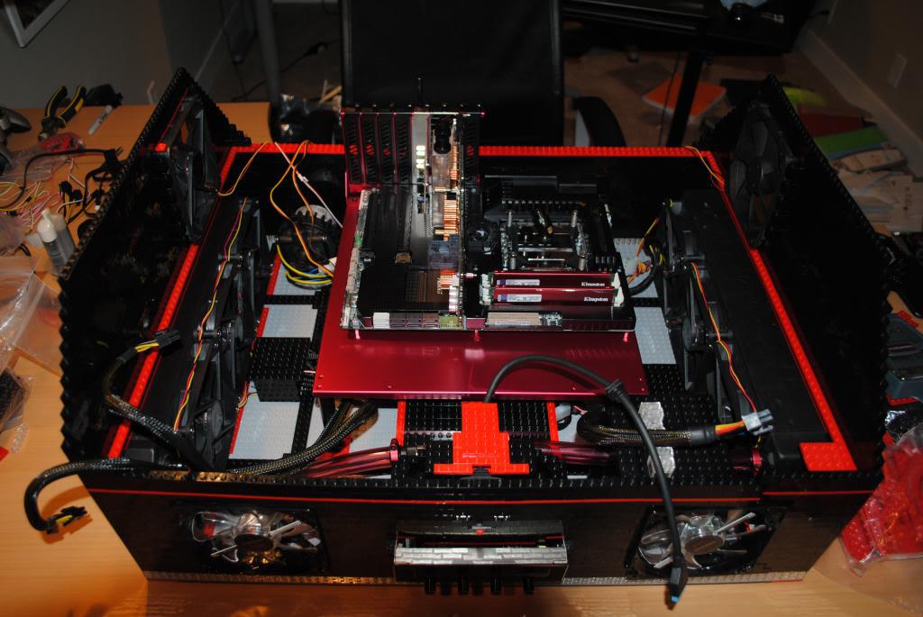
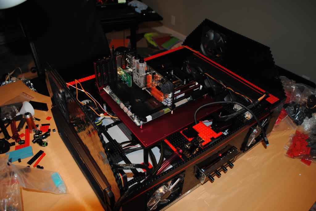
Here I did a test placement of the components. Picture taken from the rear. For those who are wondering, yes those are motherboard standoffs holding the back plate to the rest of the graphics card. The reason for this is so that I have something to grab hold of when slotting the card in and out of its slot. I wasn't comfortable using the power connectors or the PCB for leverage.

From the front
From the front corner
Finally got the case completed

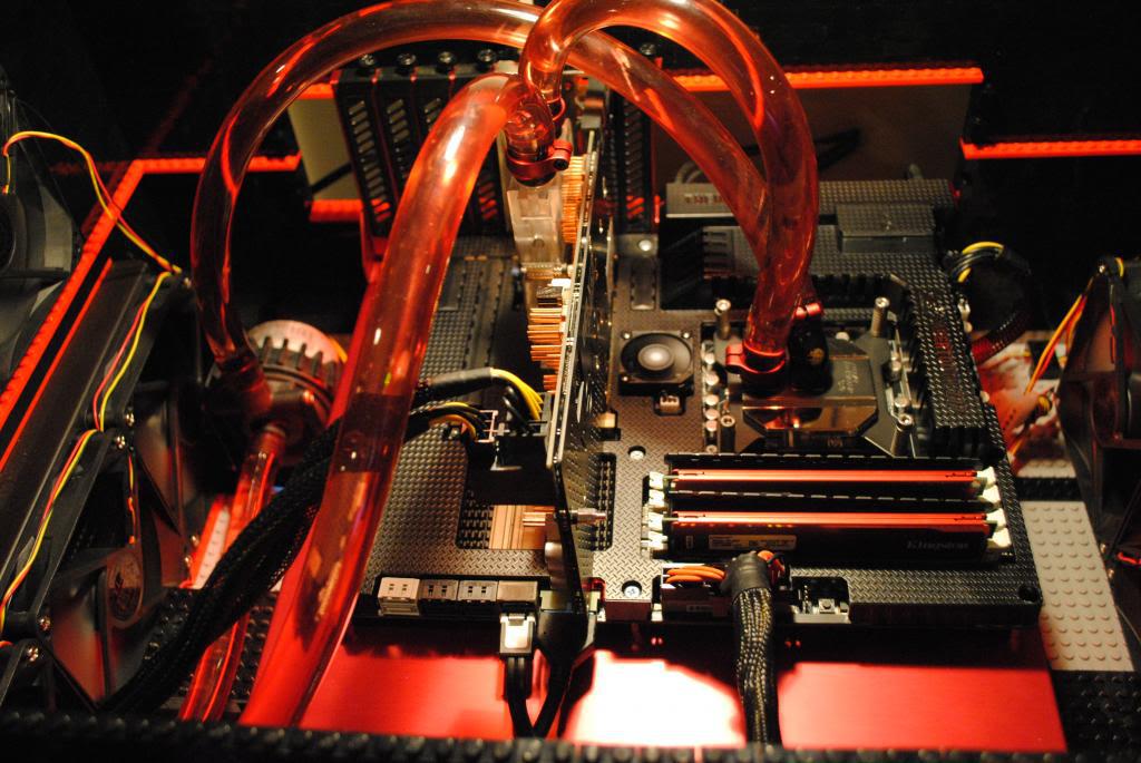
All wired up and ready to be filled. Since the beginning of the project I knew I wanted to watercool and one of the things I personally thought looked coolest was seeing dyed coolant flowing through a clear waterblock or tubing. After extensive research into watercooling I learned that dye could have some nasty effects on the rest of my watercooling components and to me that was unacceptable. I want great aesthetics but I refuse to sacrifice performance and component life in the name of looks. Coloured tubing was an option but I wasn't a huge fan of opaque colours. I wanted to see through it. After many hours of googleing I stumbled onto a forum post somewhere that showed it was possible to dye tubing. 2 packets of clothing dye, a large pot and a ruined potato masher (my roommates) I got the translucent colour you see here. The photos don't do the colour justice in my opinion.
Rear of the computer. In version 3 I made sure everything on the back panel was easily accessible.

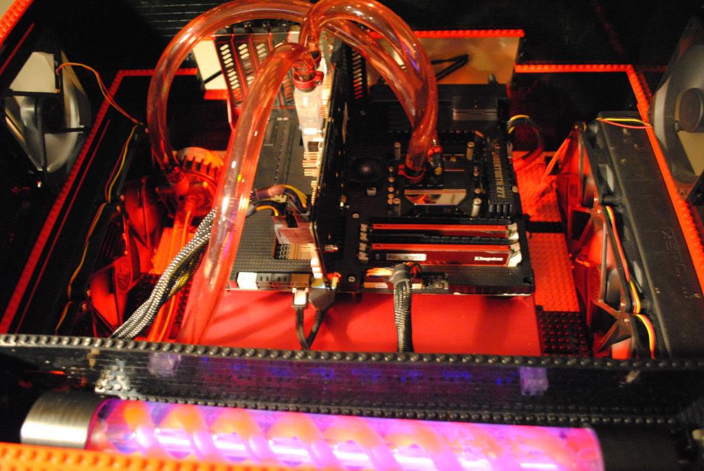
A look inside before filling the res and leak testing.

SHE LIVES!!!
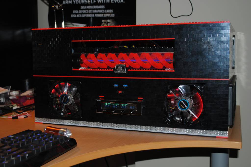
After messing with camera settings to show you the LEPA choppers. And for those who are wondering the Fan channels are as follows from left to right. Channel one: 3 left radiator fans. Channel two: 3 Right radiator fans. Channel three: 2 fans on the left and right side on the second level of case. Channel four: Pump (for some reason it wasn't showing despite the pump running properly). Temps shown from left to right: Cable management box, Gap between motherboard and tray, PSU, Pump.
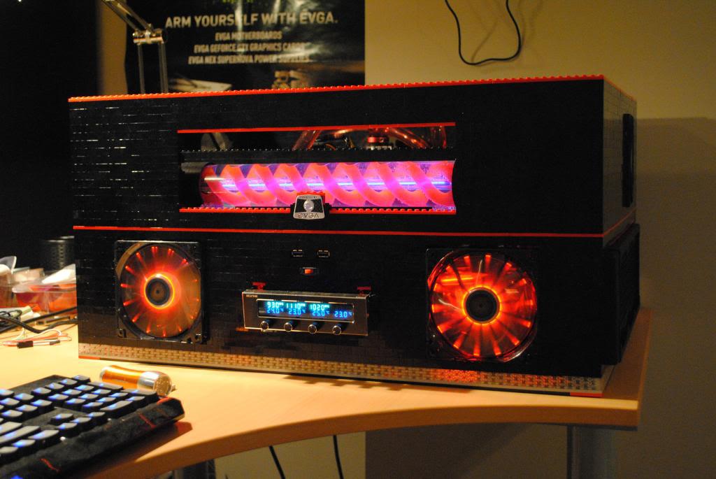
Here she is running with all lighting on. Absolutely no problems at all!
To me a huge part of the beauty of a computer is being able to see all the internals. I knew from the beggining that I would make the case open air (as reflected in my motherboard choice).
Some stats for those interested:
L:51cm
W:63cm
H:32cm
Bricks:~4500
Motherboard: Asus Sabertooth z77
CPU: 3570K
GPU: EVGA 680 FTW 4 GB
RAM: Kingston Hyper X 8GB (x2)
HD: 2TB
PSU: XFX core edition pro 850W
Let me know if you guys have any questions.