Hello!
I need somebody that knows about electrical engineering, specifically with IC’s and micro-controllers. I’m making a small circuit and it’s really nothing hard I’m just too scared to wire it myself in a schematic editor and then buy a circuit that may not work. Though i don’t need help right now i will later so please add me on discord if you can help!!
Discord: Full_Nitrous#3240
Hobby tinkerer here. What are you trying to do? Any part numbers or pictures?
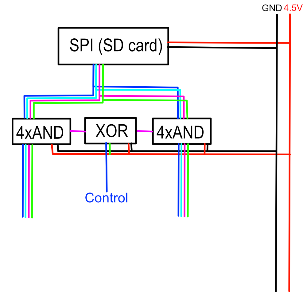
Here, I made a pseudo diagram
1 Like
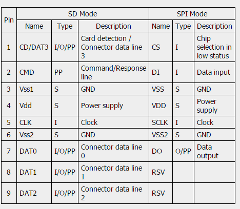
If you plan to run the SD-Card in SPI mode, you only have 4 data pins, 2 power pins and CLK to worry about.
Those 4 data pins could be switched by simply using AND gates (like SN74AC08D) which are driven by an XOR (SN74LVC2G86)
Then your controller just has to switch one line high or low to controll which side the SD card can talk to.
1 Like
Just used generic parts, but this is basically all it takes.
I have read on some sites that one should 2.2k resistors in the data lines. No idea if that is accurate.
The ready made SD card adapters have resistors inline, have to figure out values.
Edit 1: Seems there are 3 different modes an SD card in SPI-Mode runs in. Two need the pins pulled low, one needs them high.