 Introduction
This is a simple little thread to compile all the information I have about the Level1Techs DIY Keyboard kits. I know a lot of the information I will cover exists somewhere, but I wanted to give a place where the knowledge can be condensed. Kind of like the KVM FAQ I made!
Let me know if anything is missing/not clear! I’ll add it ![]()
There are 2 kits I’m going to be talking about:
- Mstar Classic Model M Controller Conversion Kit — Level 1 Techs
- Mstar Unicomp 2021 Mini M Controller Kit — Level 1 Techs
From now on, I will reference them as “classic” and “mini m” respectively.
You will need soldering knowledge and the ability to do so. Only the Mini M comes in a pre-soldered kit!
 What Are These Kits?
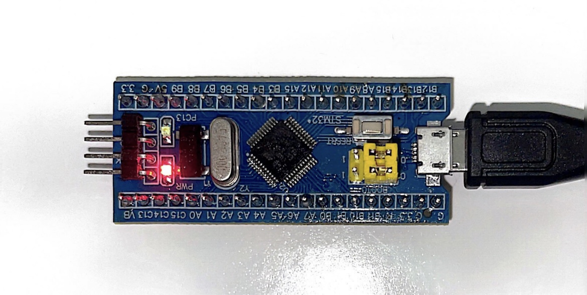
These kits are replacement keyboard controllers. They work based on the STM32 microcontroller (AKA Blue Pill). The Blue Pill is re-programmable and uses QMK firmware.
Classic
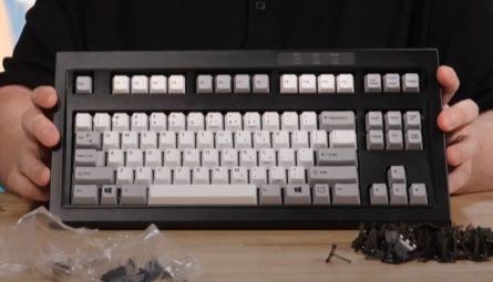
The classic kit is a converter to take your dusty old model m keyboard and modernize it with access to customization & a USB interface!
Because it is reprogrammable, you may use one of the presets listed in the QMK section, or create your own.
For this kit, you will:
- Solder your own LED jumpers.
- Solder the 5v jumper.
- Solder the 2 - 3 pins in the kit. (depends on model)
- Solder the USB-B 2.0 connector.
- Solder the Connector Tab
My goal is to give you the confidence and knowledge to do so if this kit is of interest to you.
Mini M
Unicomp’s Mini M controller is flawed. The Mini M kit/pre-soldered board is a drop-in replacement. It comes with the PCB already prepared with the proper jumpers. For the mini m kit, all you will need to do is solder the pieces in place.
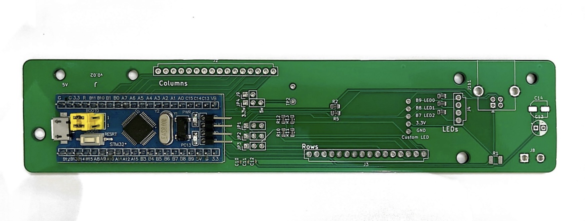
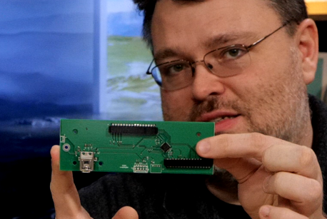
I can’t find a product link, but the mini m looks like this:
Soldering the mini-m is so much easier. Why? Because it’s always the same. (unlike the classic.)
I made a thread explaining how to solder the mini m, but, it was just for the mini m and very brief. I’m hoping to replace that guide with this one.
 All Resources & External Information
Wendell & Eric Raymond have a Gitlab repository with information & their process:
-
Information about the included Blue Pill can be found here:
STM32F103C8T6 - Blue Pill | STM32-base project -
A simple educational article about good-practice soldering:
9 Essential Electronics Soldering Tips and Tricks for Beginners - National Aviation Academy
Classic
This installation can be tricky! Luckily, Wendell did create a great video explaining the process:

- Eric Raymond documented his experience assembling the Classic controller:
web/classic-installation.adoc · main · Eric S. Raymond / M-Star · GitLab
Mini M
In addition to the classic, Wendell made an introduction video on the subject as well. In this video he solders and will give you a foundation of knowledge:

In Wendell’s own thread you can find resources:
- Eric Raymond documented his experience installing the mini m controller:
web/mini-installation.adoc · main · Eric S. Raymond / M-Star · GitLab - Eric Raymond also has a write-up about customizing your mini m:
web/mini-customizing.adoc · main · Eric S. Raymond / M-Star · GitLab
 Mstar Unicomp 2021 Mini M Controller Kit
What’s Included:
- 1x Unicomp 2021 Mini M QMK Replacement Controller PCB
all surface Mount resistors and capacitors are pre-soldered!
- 1x Blue Pill
- 2x 16 Pin Connectors
- 1x USB-B 2.0 Power Connector
 Before you Begin
Smoke Test
Eric Raymond recommends doing a “smoke test.”
If your L1T mini m controller is working properly, you will see a red light turn on the blue pill. After a few seconds, another light will appear. If this does not happen you could have a bad cable or possibly a faulty controller.
Try a different cable and different port on the PC to troubleshoot.
Thank you @mattaw for this suggestion for the smoke test:
You can download the QMK Toolbox here → GitHub - qmk/qmk_toolbox: A Toolbox companion for QMK Firmware
Once you install it, open it up and plug the blue pill in. You should see something like this:

^ This is a good sign your blue pill is working as intended.
What You Need
- Soldering experience (recommended)
- #1 Pozidriv or 7/32-Inch Hex Key screwdriver to open the back (depends on your mini m)
- Soldering iron + flux
- A small piece of bendable metal wire (eg. a bread tie, paperclip)
- A USB-A to USB-B 2.0 cable
^^ not to be confused with a USB-A to USB-B 3.0 cable

 Assembling Your Mini M Controller
Place the included blue pill, 16-pin connectors, and USB-B connector into the through-pin holes on the PCB, and solder the backside where the pins poke through.
Blue Pill
Orientation matters!!
The Blue Pill needs its 4 pins to be facing in the direction shown in the reference picture.
16-pin Connector
USB-B 2.0 Connector

This piece will require quite a bit more solder than the others. Make sure you are adding an adequate amount for a good connection.
Removing the Original Controller
Now, you’re ready to open your Mini M up and get started!
When you remove the original controller, it should be pretty straightforward. Be mindful of gently pulling out the ribbon cables. Any damage could cause it to work incorrectly.
Installing the Mini M Controller
Place the controller inside the back of your Mini M. Two plastic guides will show you where to set the Mini M. The USB-B 2.0 connector should be resting between them.
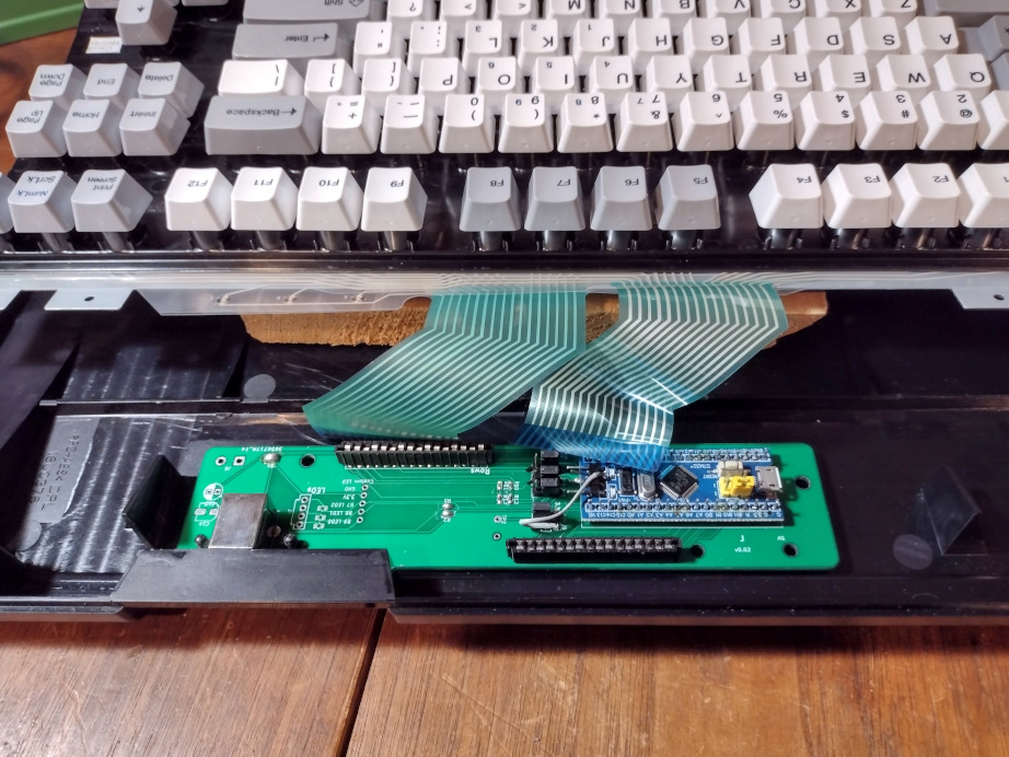
Ensure your ribbon cables are completely in the Mini M controller. The USB-B 2.0 connector should be lined up with the opening in the case.

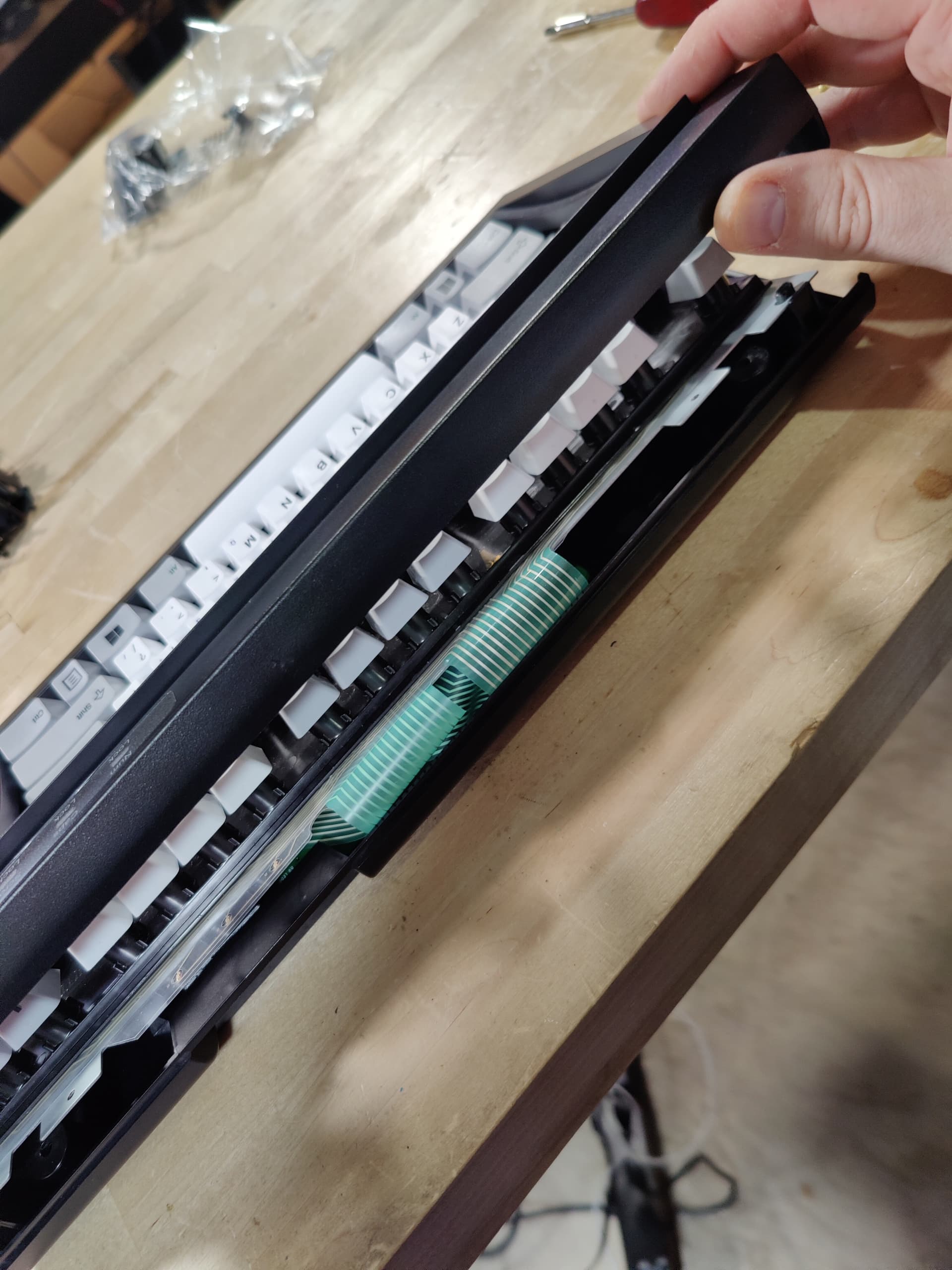
 Reassemble Your Keyboard
Be careful to not crush, bend, or crease the ribbon cables while you’re reassembling your Mini M. It can be easy to do! Make sure your keyboard is slotted correctly into the plugs on the case.

Once this is done, just put the top back on and you should be good to go!
Mstar Classic Model M Controller Conversion Kit
What’s Included:
- 1x Model M Universal QMK Replacement Controller PCB
all surface mount resistors & capacitors are pre-soldered!
- 1x Blue Pill
- 3x [Your Choice] Pin Connectors
- 1x USB-B 2.0 Power Connector
- 1x 3D-printed Power Adapter
Before you Buy
Before you buy the classic kit, you will need to know what pin configuration you need. We have 3 configurations to choose from:
- 16+12+4
- 20+8+4
- 16+8+4
Some Model Ms will require a 4-pin connector, some won’t. Just don’t use the 4-pin if that is the case for you.
To determine which configuration you need, you’ll need to open up your model m.
Opening Your Model M
-
Start with your Model M flipped over so that the keys are facing the table.
-
At the top of the back of the keyboard, you will see 4 hex screws you will need to unscrew.
-
Once screwed, gently pop the halves apart and lift the back away from you to open the back of your keyboard.

Once the screws are out be very careful!
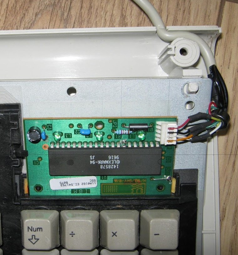
You will be greeted with a controller that has 2 ribbon cables attached to it. These cables are slightly fragile and should be handled very gently. A crease or tear in them will ruin them.
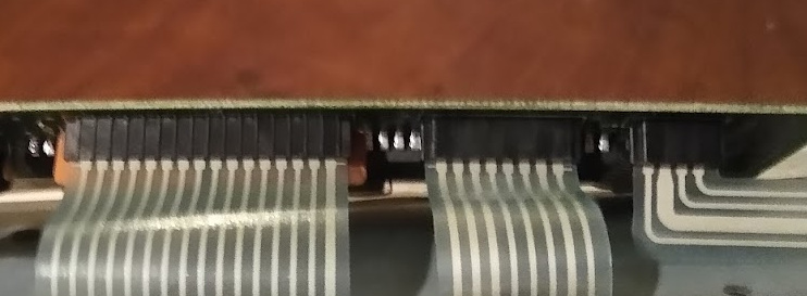
Check Your Controller

What you see will vary depending on when your Model M was made. Various connectors, resistors, and colors. The important parts you’re looking for are the connectors the keyboard ribbons are plugged into.
Count the pins to see which configuration you will need to buy.
If you have a physical 4-pin ribbon, you will need to use the included 4-pin connector in the kit.
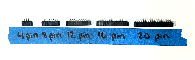
Pin-Connectors Reference
Controller Special Cases
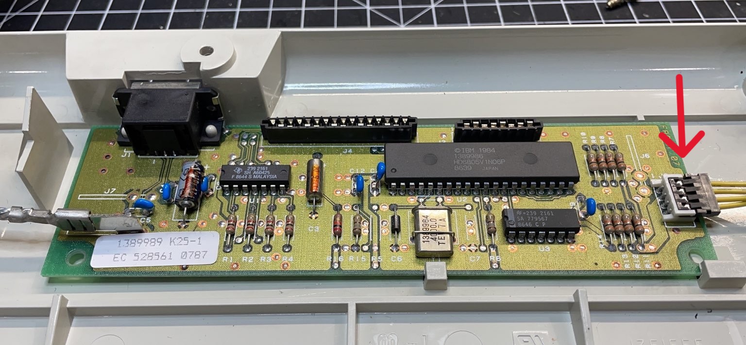
-
4-Pin Connector is a header, not a ribbon
This Model M controller has a 4-pin LED header, but it is not a ribbon. If this is what yours looks like, please contact us (wendell at level1techs dot com) so we can give you the proper 4-pin header!!
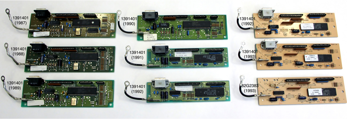
-
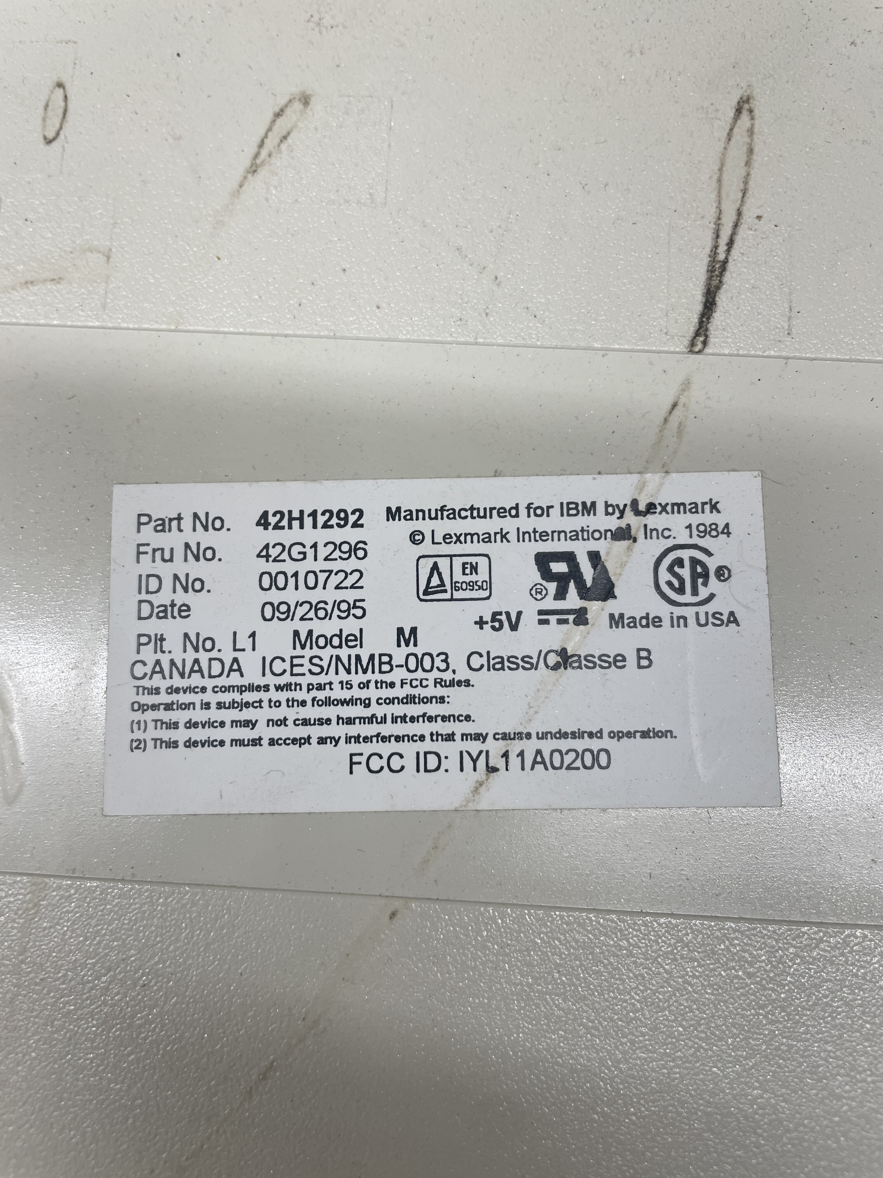
 Incompatible
-
Something like this indicates you have a later-made Model M and unfortunately it will not be compatible with the classic kit.
-
This keyboard is incompatible.
Now you know what your pin situation looks like, you’re ready to buy!
Before you Begin
Smoke Test
Eric Raymond recommends doing a “smoke test.”
If your L1T classic controller is working properly, you will see a red light, then after a few seconds another light. If this does not happen you could have a bad cable or possibly a faulty controller.

To troubleshoot, try a different cable and/or different ports on the PC.
Thank you @mattaw for this suggestion for the smoke test:
You can download the QMK Toolbox here → GitHub - qmk/qmk_toolbox: A Toolbox companion for QMK Firmware
Once you install it, open it up and plug the blue pill in. You should see something like this:
^ This is a good sign your blue pill is working as intended.
What You Need
- Soldering experience (recommended)
- A 7/32-Inch Hex Key screwdriver
- Soldering iron + flux
- A small piece of bendable metal wire (eg. a bread tie, paperclip)
- A USB-A to USB-B 2.0 cable
^^ not to be confused with a USB-A to USB-B 3.0 cable
Assembling Your Classic Controller
Solder Parts Into Place
Place the included blue pill, 16-pin connectors, and USB-B connector into the through-pin holes on the PCB, and solder the backside where the pins poke through.
Blue Pill


Orientation matters!!
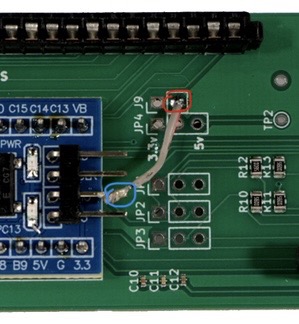
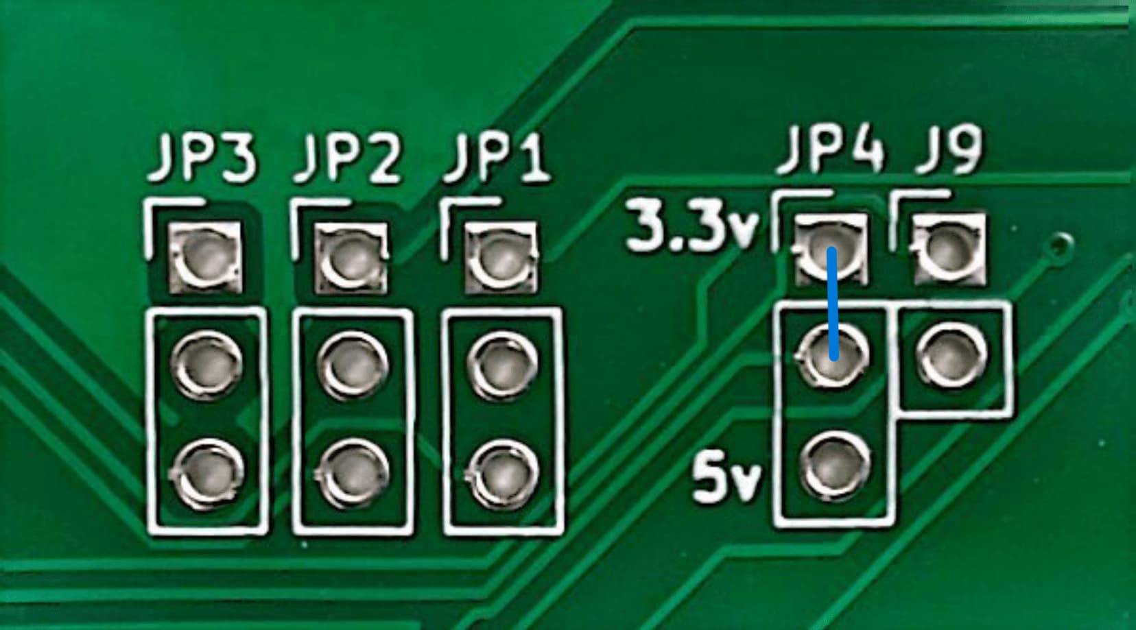
The blue pill needs its 4 pins to be facing the direction shown in the reference photo. Also, you will need to solder a small wire to the 3rd Blu Pill pin to the lower through-hole in J9.
USB-B 2.0 Connector

On the classic boards, there are 2 places available to solder the USB-B 2.0 connector (left or right side) both sides have the jumper pre-soldered so you may place it on whichever side lines up.
This piece will require quite a bit more solder than the others. Make sure you are adding an adequate amount for a good connection.
Soldering Jumpers
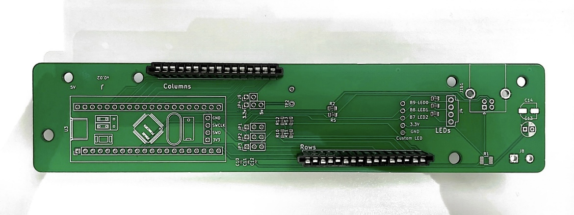
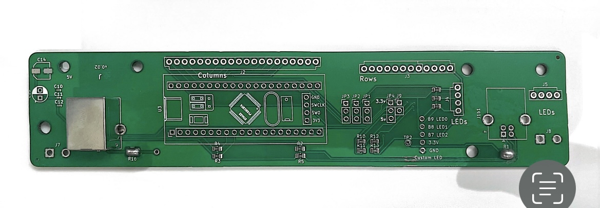
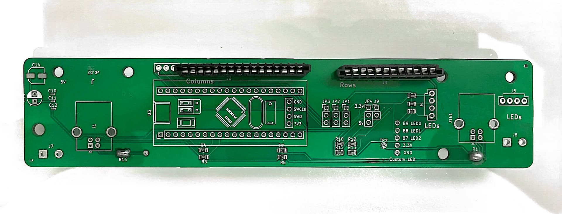
Reference
If you have the know-how, here is the PCB layout from KiCad. It will show you which jumpers need to be soldered:

- JP1, JP2, & JP3 - LED jumpers (based on pin configuration).
- JP4 - power jumper.
- JP9 (lower) - where your metal wire will connect to your BluePill.
Use the list below to solder the jumpers accordingly.
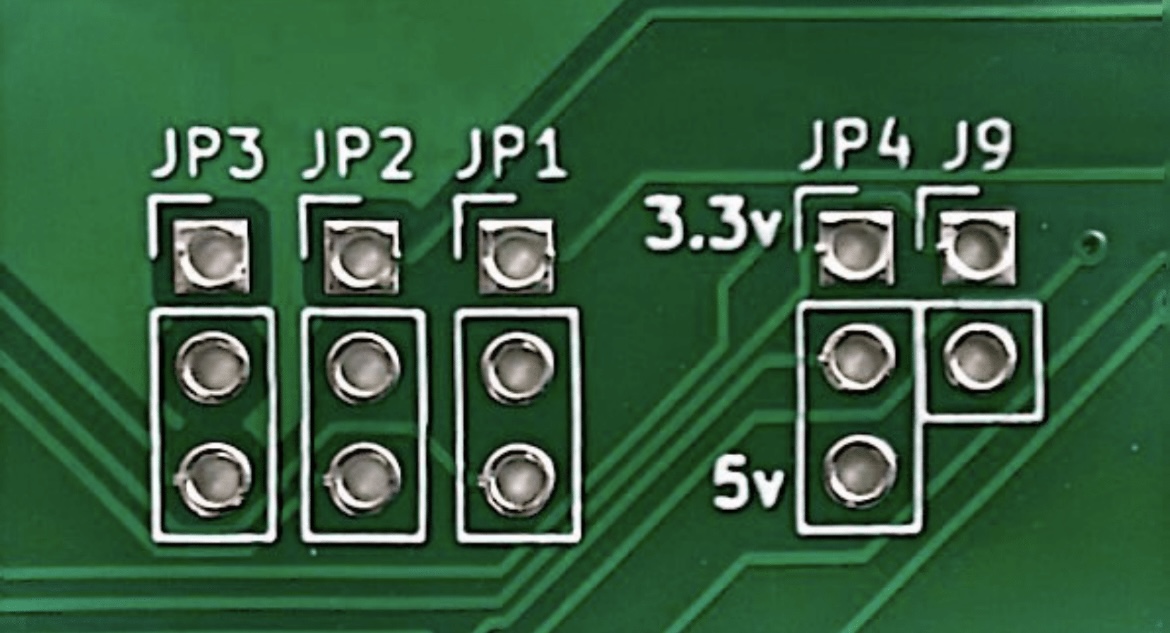
JP4 (Power)
You have two options: 5v or 3.3v. If unsure, solder 5v.
3.3v would be soldered only if you have a reason or special Model M.

Different Pin Configurations
The jumpers you need to solder depend on which configuration you bought. Therefore, I will go through various configurations. If you have an unaccounted-for model m type, please let us know!! I will add it to the configurations list.


Removing the Original Controller
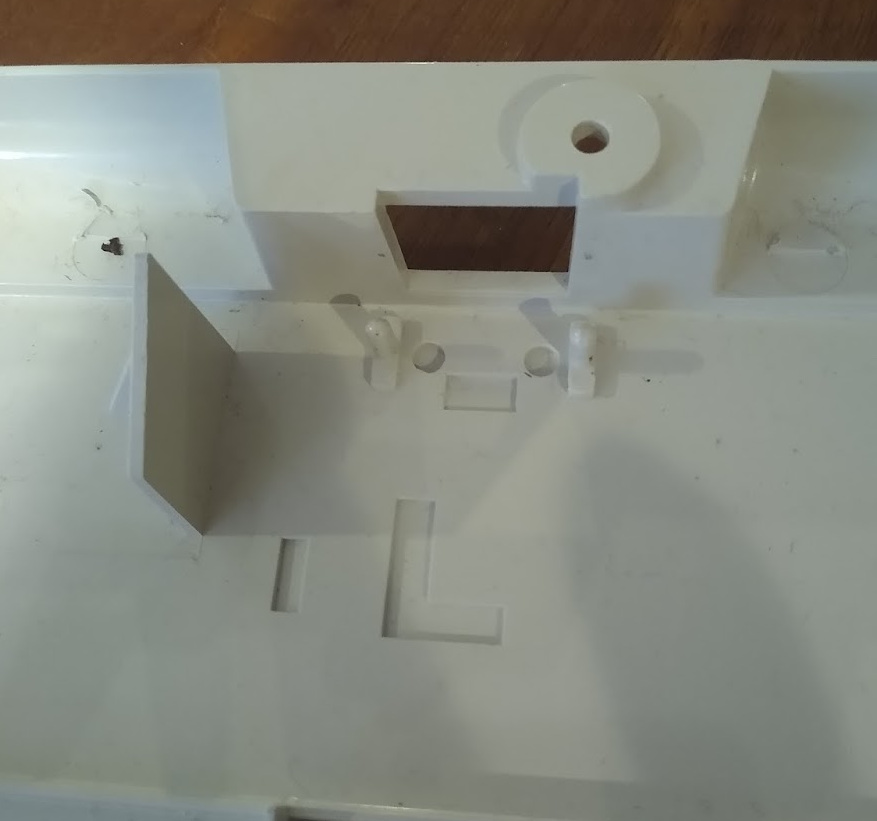
When you open up your Model M to take the controller out, you will be greeted with something similar to this.
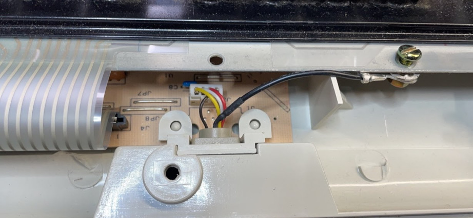
The included 3D-printed adapter goes in place of the white one you see here. You may remove the original Model M cord and all cables/wires attached to the cord. Those are not needed.
Wiggle and take off the ground connector attacked to the connector tab, you will need to put this on the new controller.
Installing the Classic Controller
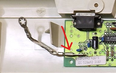
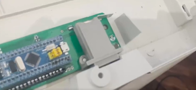
You should see something to this effect once you take out the original controller
You will see 2 plastic guide pegs on the back of the model m. With your PCB in place, you will be able to place the 3D-printed power adapter and have it fit snugly and flush to the port cutout.
Reassemble Your Keyboard
Make sure to screw in the ground connection “tail” into the frame.
Carefully reconnect the ribbons to the new controller. Once that is done, ensure your keyboard is in the frame property before closing anything up. Any creases, cuts, or tears in your ribbons while closing the case could damage them.

Just put the top back on (carefully) and you should be done!
QMK Presets
These controllers are re-programmable. So you may use your own QMK layout, or, on the Gitlab page there are a some different presets for your Model M.
-
Default - Uses a ‘standard’ layout.
- This is what’s pre-flashed on all Classic orders. If you have one of the cases below (AT 122 or M 122) you may need to flash to those from this ‘Default’ preset.
- Scroll Lock is reserved on Linux, enabled on Windows.
-
Mini M - Uses a ‘standard’ Mini M layout.
- This is what’s pre-flashed on all Mini M orders.
- This is what’s pre-flashed on all Mini M orders.
-
Wendell - Wendell’s preferred layout.
- Caps Lock: Pressing left and right shift at the same time.
FN Layer Commands (Press and hold Num Lock): - Pause = Mute
- Scroll Lock = Volume Down
- Print Screen = Volume Up
- Caps Lock: Pressing left and right shift at the same time.
-
AT 122 - For keyboards with the (20 + 8 + 4) pin configuration.
- M 122 - For keyboards with the (20 + 8) pin configuration.
QMK Customization
I made a “How-to” style post for flashing the bootloader and QMK on Windows/Linux. All of the other information for how they made the different presets will be on the Gitlab page.
If you want to flash Wendell’s preset instead, or flash your own custom preset, I recommend giving it a look!
 FAQ
FAQ
Some people have reported having trouble with the LEDs being backward after installing the classic kit.
Update:
This problem has been fixed! The proper QMK flash will be on new controllers sent out, but if you do have an old version, the Gitlab is up-to-date!
Old Solution
Thank you to @Bryson_Osborne for your code suggestion!
bool led_update_kb(led_t led_state) {
bool res = led_update_user(led_state);
if(res) {
writePin(led_pins[0], !led_state.num_lock);
writePin(led_pins[1], !led_state.caps_lock);
writePin(led_pins[2], !led_state.scroll_lock);
}
return res;
}
 Thank you
As Wendell said previously, we are considering this an open-beta level of testing for this product. It is not perfect, but it is pretty darn good. Please let me know of any more issues you have and if I can be of help.