First embedded hardware hacking project w/ pictures - at the edge of a rabbit hole

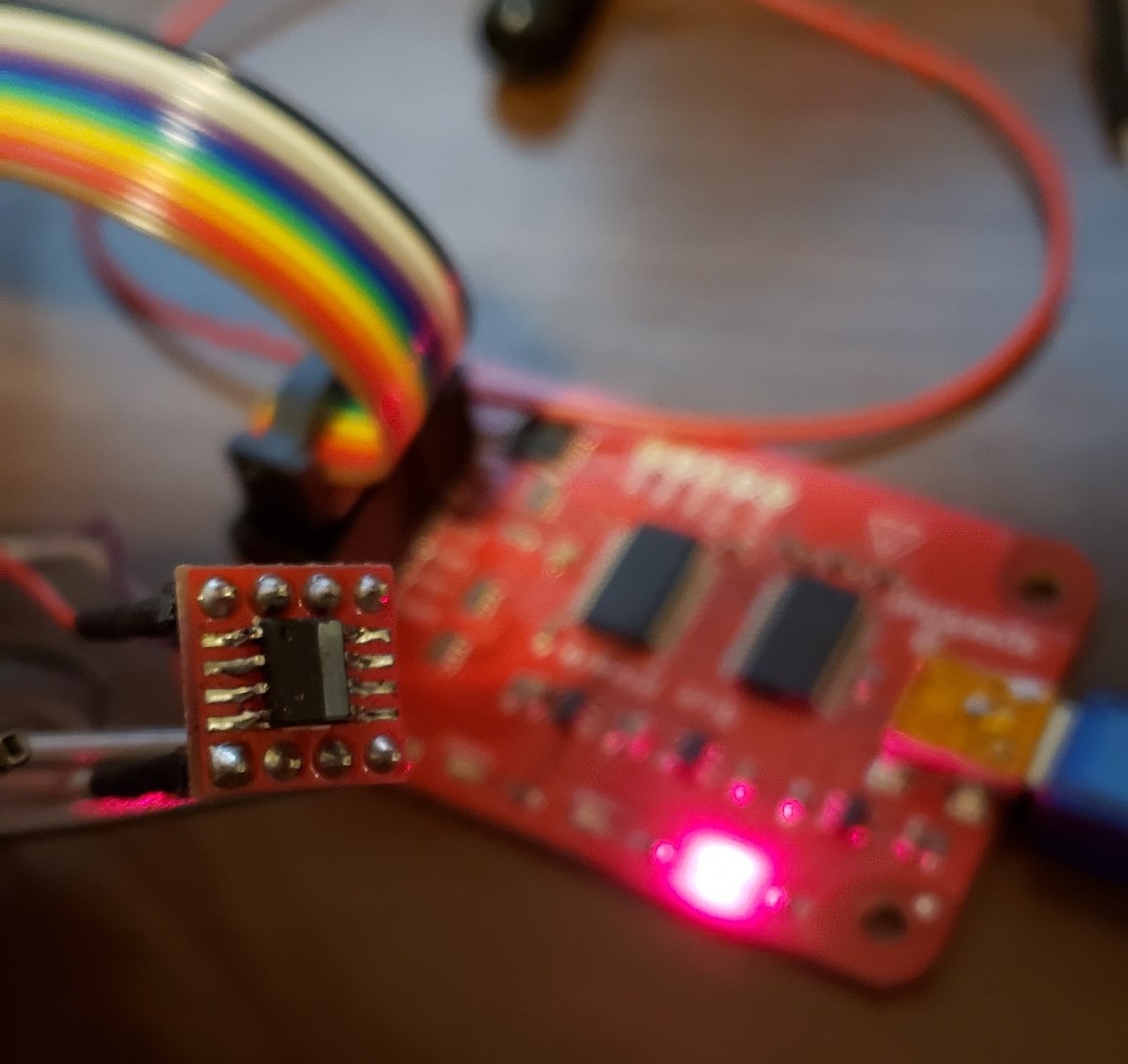
I bought a ~$20 RC quadcopter earlier this year. It has an onboard camera that streams live video to a smartphone app by broadcasting it’s own wireless network that you then connect to. Surprise! It sucked. But I saw that the onboard camera was it’s own module connected to the quad only by three wires. There were also clearly labeled test points for SWD and Tx/Rx signals. I decided give this thing a shot to see if I could learn what makes it tick.

First step was to connect my JTAG programmer to the exposed SWD signals and see if I can dump the camera’s firmware. Say hello to Kyle.

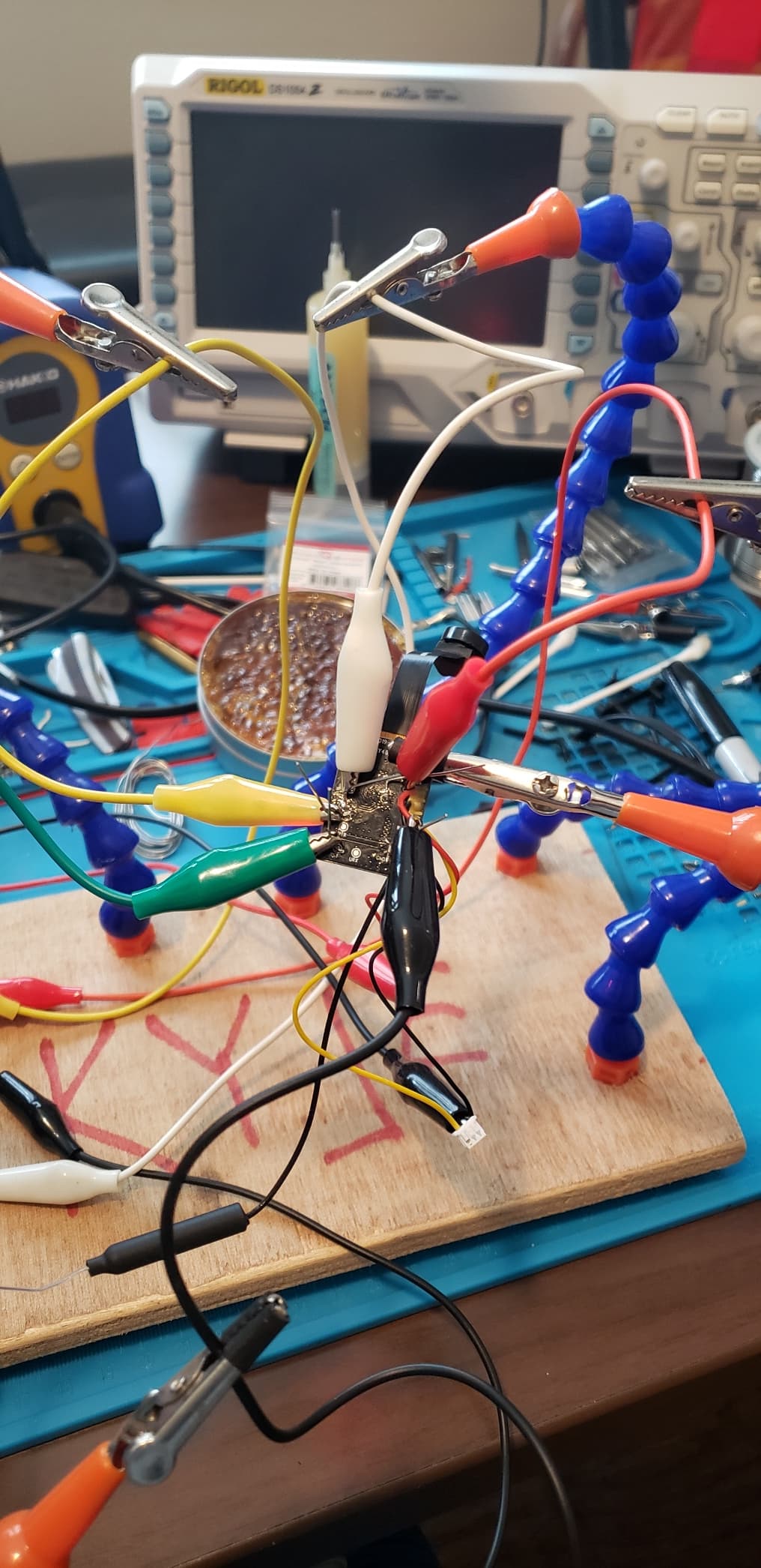
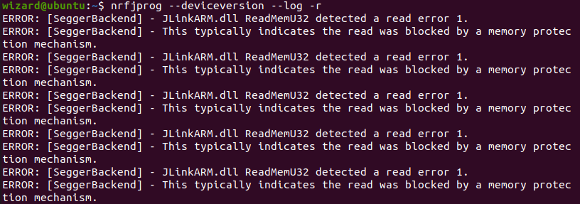
The chip ended up being read protected. Turns out this toy wireless camera has better security that many modern wireless routers.

Were I to RTFM I may be able to get around this, but I decided to focus on the Tx and Rx pins first. The only UART to USB device that I have an an arduino uno that I borrow the FTDI Tx/Rx pins from.

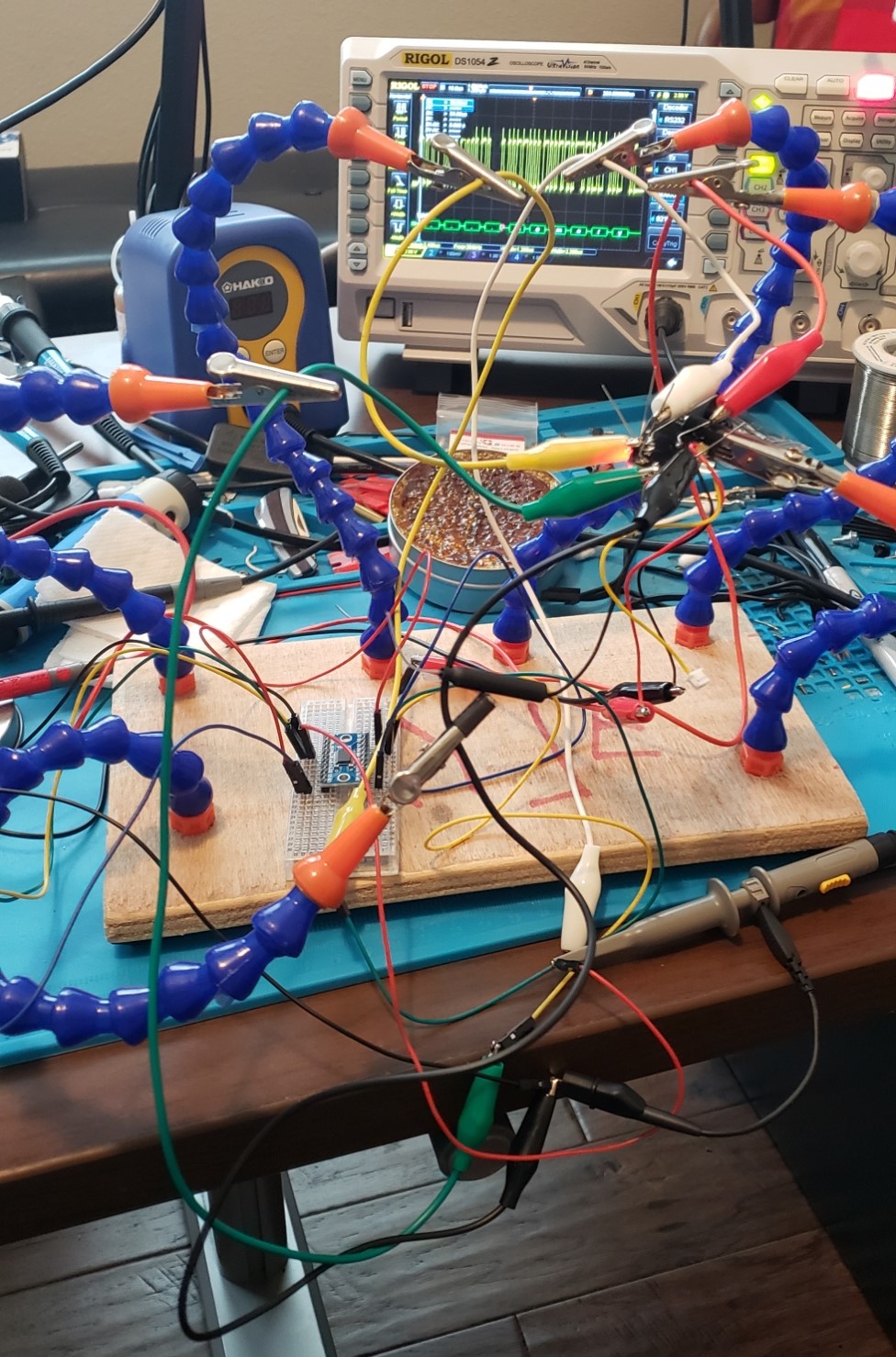
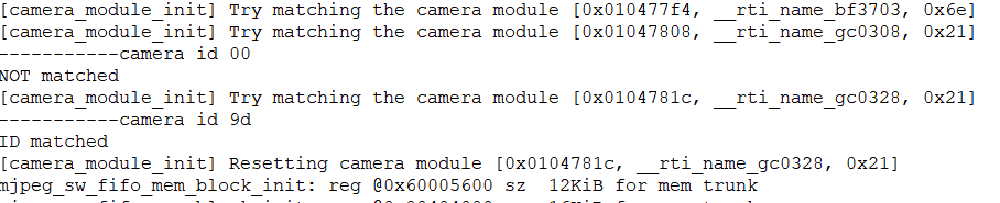
The first part of this was easy enough. Open a terminal and use Screen to watch for a signal on /dev/ttyACM0. At 115200 baud I was met with a few lines that looked like status messages during a boot process and then gibberish, so the chip is switching to a different baud rate after it boots.

This was where things got interesting, as I quickly learned that none of the ‘normal’ baud rates were being used. This is uncharted territory for me.

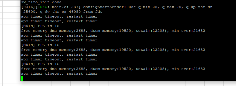
I started by just screwing around with my scope’s decode features that I had never used up to now. After blindly scrolling for a bit, I used the Single feature of my scope to capture some amount of data being transferred at this mysterious baud rate. Once sufficiently zoomed in I was able to measure the length of time that it took for a single bit of data to be transmitted at 1.100us. My calculator says that a 1.100us long ‘1’ correlates to 909090 baud, so I stuck 909000 into the RS-232 decoder and . . .

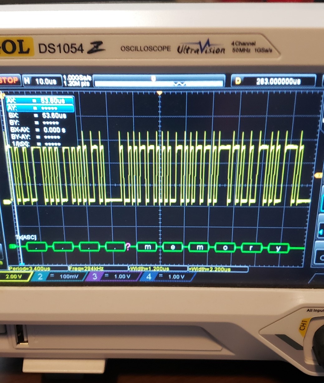
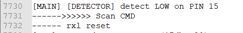
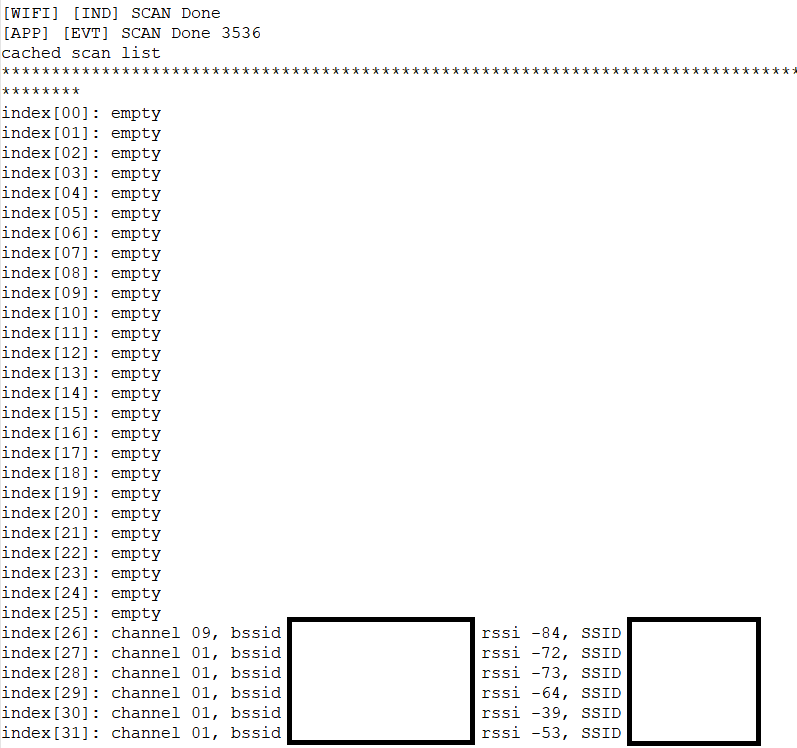
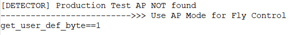
Voila! Scrolling through this data it turned out to be some kind of device status including things like FPS and memory available.

Getting a live feed of this data on my PC hasn’t been nearly as simple. From what I have read so far, it seems that using non-standard baud rates in linux isn’t natively supported at all. Specifying 909000 baud in something like Screen only outputs garbled characters, which made me suspect that the specified baud rate wasn’t being honored. I saw some information about baud rate aliasing that may allow me to get around it but I haven’t given that an honest go yet.

This is where I need to consult the elders. Could this be a limitation of the arduino FTDI chip? Is there some user-friendly way to force custom baud rates that isn’t as destructive feeling as aliasing? I’m using ubuntu for this project but I can spin up a VM of whatever if there is a good solution to be found elsewhere.

Is there a particular standalone USB to Serial device that that is better suited to this task? I’m always glad to have an excuse for a new tool.

Edited for spelling and brain cramps.

5 Likes

This thing has worked for me most of the time.


Edit: Maybe this helps?

Has been a while since I last fumbled with cameras in combination with arduinos.
It may be possible to modify some library so the Arduino talks in a different rate to the camera.

I’ll add that thing to the list, thanks for the tip.

I haven’t done much research on the actual MCU on the camera module yet, but I did look at it long enough to make sure it wasn’t something familiar like an ESP32. That would have been too easy!

1 Like

I looked into baud aliasing more deeply. As far as I can tell, the atmega16u2 that my arduino uses as it’s usb-to-uart bridge is limited to whole number divisors for UART clock generation. FTDI chips like the one linked above can get as granular as 1/8th of whole numbers (1.125, 7.875 etc. . .) which would get me within the necessary 3% of my target and stands a chance of working.

Does a device exist that can utilize arbitrary baud rates? There must be.

I mean… technically maybe? Just have to learn VHDL… (which is why I have that above board, safely packed away, because I can’t even in VHDL!

I’ve had my eye open for a project that would benefit from an FPGA, but somehow I don’t think this is it lol

For anyone else asking this question later, the two most capable USB-Serial chips (as far as divisor granularity) that I’ve found are:

TI TL16C750E, capable of 1/64th fractional divisors
TL16C750E data sheet, product information and support | TI.com

Cypress CY7C65213, capable of 1/32nd fractional divisors
https://www.cypress.com/documentation/datasheets/cy7c65213-usb-uart-lp-bridge-controller

I haven’t found a product that uses the TI chip, but sparkfun conveniently makes a USB Serial breakout that uses the Cypress chip.

Same.
Is just that I have that red board sitting on my desk reminding me to finally put in the work to get something out of it :neutral_face:

Seems like an easy choice then.

The closest I ever got to buying an FPGA board, I can’t remember exactly the project but I was looking for the lowest latency option for something. That’s definitely the low latency everything option but MAN is that a bear of a learning curve.

1 Like

Learning C is banging your head against a wall, my two dips into VHDL felt like trying to scratch tungsten carbide with wet cardboard.

Victory

2 Likes

Much to my disappointment I wasn’t met with a root terminal. I did, however, get a verbose flow of status information all through the initialization process and I did learn a few interesting things:

The first thing it does is check for voltage on pin 15:
pin15

Then after it set’s transmit power it scans for any wireless networks it can find and caches them.

Then it tries to connect to a specific production test AP. No hint as to an SSID.
Test_AP

And finally it attempts to initialize a couple different camera modules. Seems like a smart way to handle using whatever module is cheapest/available without having to make any changes during production.

1 Like

I’ve pulled the NOR flash module from the board and have it connected to my new Bus Pirate.

After spending some time with it, I understand now that this chip isn’t yet supported by flashrom. I did some quick research and the first SPI programmer I looked at, SF600, didn’t support it either.

So what’s the next step? No idea really. I DO have a datasheet, so that’s about the best starting point possible I guess. This seems to be the turning point where I either commit to understanding accessing NOR flash at a more fundamental level OR I add this one to the art bin.

2 Likes

After a little time in the datasheet and more than a little time in the flashrom docs, I learned how to do this:

fentech_id

new_chip

And then did this:

Read successful baby! All I needed to do was create a custom device in flashrom so that it ‘recognized’ the chip and reading it’s contents just worked. I left erasing and writing for another day. Next step is to figure out what to do with the hex file so that I can unpack it’s secrets.

EDIT: Preliminary attempts reveal that this part isn’t going to be easy either FAHK

1 Like