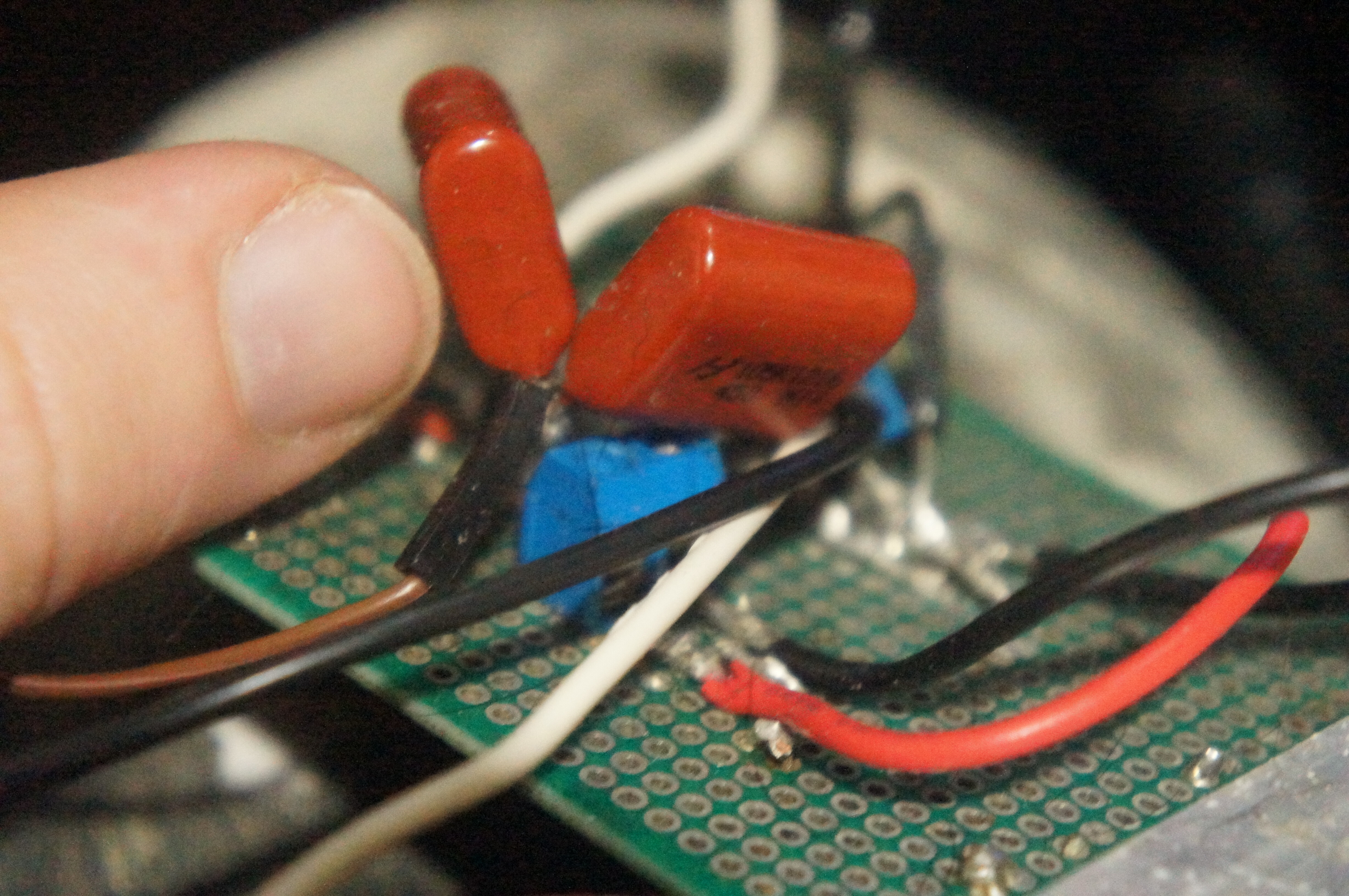
A couple Comparators, MOSFETs and MOSFET drivers. Only running off one MOSFET in the video.

A couple Comparators, MOSFETs and MOSFET drivers. Only running off one MOSFET in the video.
I assume your amp does simple open-loop PWM.?
I believe that is an accurate assumption. I’ve only heard of power stage feedback and don’t know how that mechanism helps… baby steps.
Feedback is used to improve the linearity and with it, you also get the ability to perform noise shaping.
Interesting!
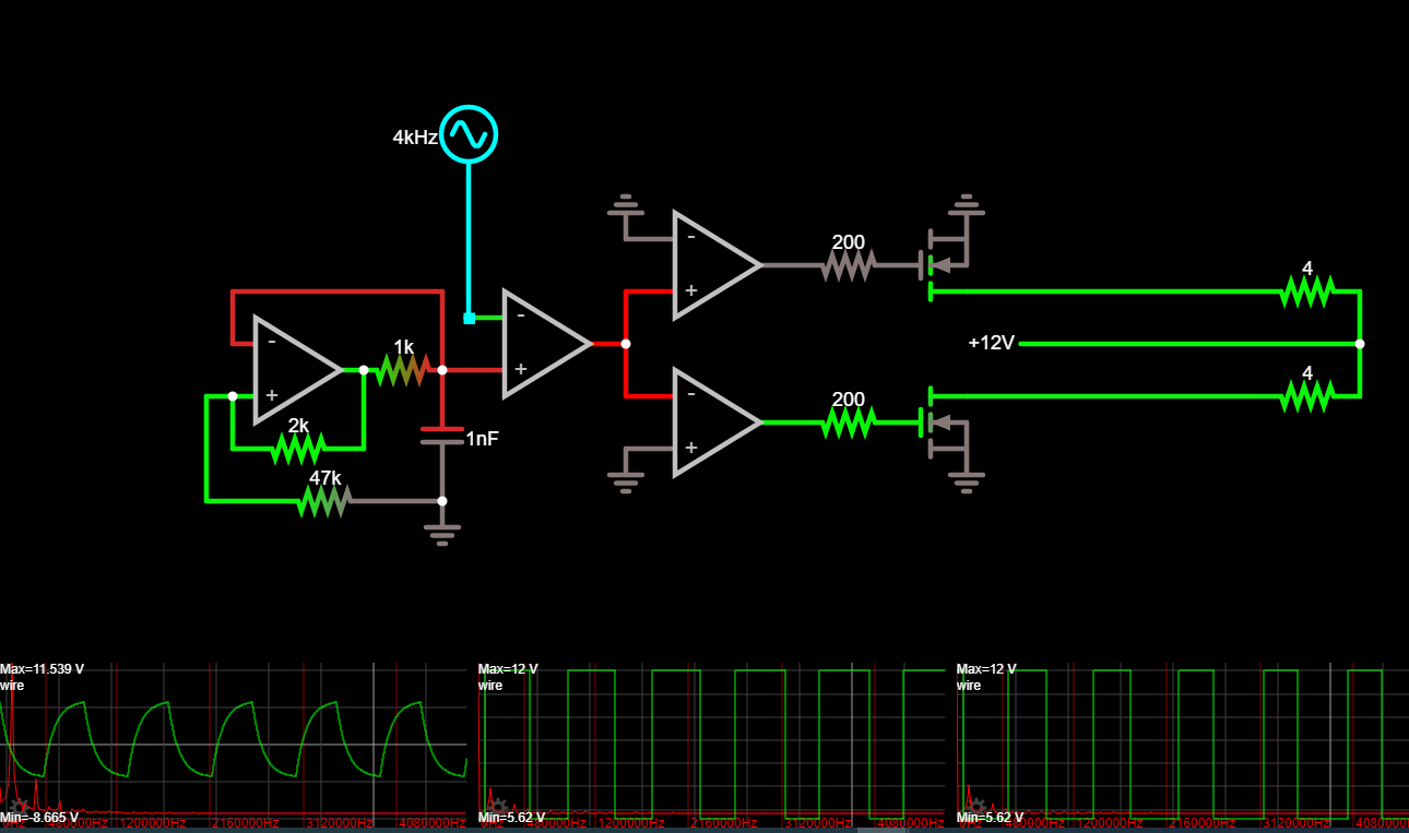
Do you have a circuit or block diagram?
Concerning the Op-Amps: Make sure to have current limiting on inputs and outputs as well as over voltage protection on their power input.
Let’s continue that discussion, shall we?
In general, you should only add resistors if they are actually necessary, because all resistors are inherently noisy and they can also lower your bandwidth or in extreme cases lead to instability.
So, when are current limiting resistors necessary? Whenever you expect high differential input voltages with bipolar op-amps, which should never be the case under normal circumstances, unless there is an abnormal amount of transients present, in which case, other protective measures might be more appropriate.
To get back to the topic of the class D amplifier: There are only comparators in this circuit which are designed for high differential input voltages, so no need for current limiting resistors.
Quad comparator- https://www.ampslab.com/PDF/tl074cn.pdf
MOSFET drivers- http://ww1.microchip.com/downloads/en/DeviceDoc/20001987C.pdf
MOSFETs- 24N60C3 pdf, 24N60C3 description, 24N60C3 datasheets, 24N60C3 view ::: ALLDATASHEET :::
Simulated circuit- http://falstad.com/circuit/circuitjs.html?ctz=CQAgjOB0AMAsYDYnJUg7AUwLRpNSATAtGgMyxoFpinQCcRaupCIrArNCO9mGAFAB3EFgIFYIWKQIixE2AgnQhIsLHmJV6yYrz8ATlvm7R4nUpAFo1lafnTZsLlJnLhop5IcfndVssMfST8RENgQ5zRrAKNJTSwwzS4waP4AY1DWeFYErIjwbDo2SAAOJCsxKIZxUlI8GGgBd0SckJYSvWbWdtkzHrdeiR67SWs9AHNM4NaOMFcJyz6WRaGrPD0AM3A0bvYZORBSPdHD+ugCfi2wHclYDoP1Doc6-HP+ACVzUa5xZzGuP7geYAyDsAxAp7Ha67eZWGJzDqPbZZO7rOH8SaaBQSLElAELTS1ViEtYA-gAQxEeO+4CyYw6YHYqiZKWiYywYEgfkQJXY7BKtEZ9AIdQQpXK5yowpqdVZqUpI2ysSVDJkCXAbLGYrKCAqUuqUjqWBKkAQ5BodBKYDK7G5MjlNkphKhBEhMnu+Id-3A7Aa0BKJSoZDQvNIIS9FNpt1ViNRHvWXuSvuiAaDpBD7DD-g1bI+VK4pBKEmNP0oCe+XCZ+PwYMmD10D2pZMMTgLCERun6knB2K8MlbffWsBUBx6A-6KgHLhWg4GJbiMwXnSjPSx-xUWIca7Jwl7Y90A4GvanB4cygA9iAGetMyHLCCID8r4d+JfXeAE0couBOXQ-3+A3IAh+QYM5rAgCB9ieV9LCKR9wC-ZJf3-S0BVgYCSlA15wMsXCCCKUh+CAA
The datasheet for the comparators claims infinite short circuit capability for outputs and shows 300 ohms of output impedance… but, some stopped working.
Oh, and the potentiometer is in place of the 1k resistor, I also swapped the capacitor for a smaller one, seemed to help a little.
The question is, did it stop working under normal operation or was there a short? Another likely cause are voltage spikes on the supply lines caused by the back-emf of the speaker. Adding some large bypass caps along with smaller ceramic ones should help with that.
I had a look at your schematic. One way to greatly improve the linearity would be to replace the oscillator with a proper triangle wave generator. Also, a bit of hysteresis should help reduce random switching which would intern reduce voltage spikes.
I’m not quite sure how your power stage design works. Are you using both MOSFETs to drive one speaker or are you driving two speakers at once?
When the spec sheet has resistors on the input and output, I regard them as necessary.
I have looked at the datasheets of a lot of op-amps and I have never seen them mentioned anywhere.
Also, what might look like a current limiting resistor could in fact be there to compensate the input bias currents.
Data sheet showed the resistors as part of the IC.