Hi guys,
Can someone give me a general overview of what this circuit is doing and how I go about getting values for R1 and R2?
Edit: Read through all replies guys and I have a better understanding of what is going on. Thanks very much
Hi guys,
Can someone give me a general overview of what this circuit is doing and how I go about getting values for R1 and R2?
Edit: Read through all replies guys and I have a better understanding of what is going on. Thanks very much
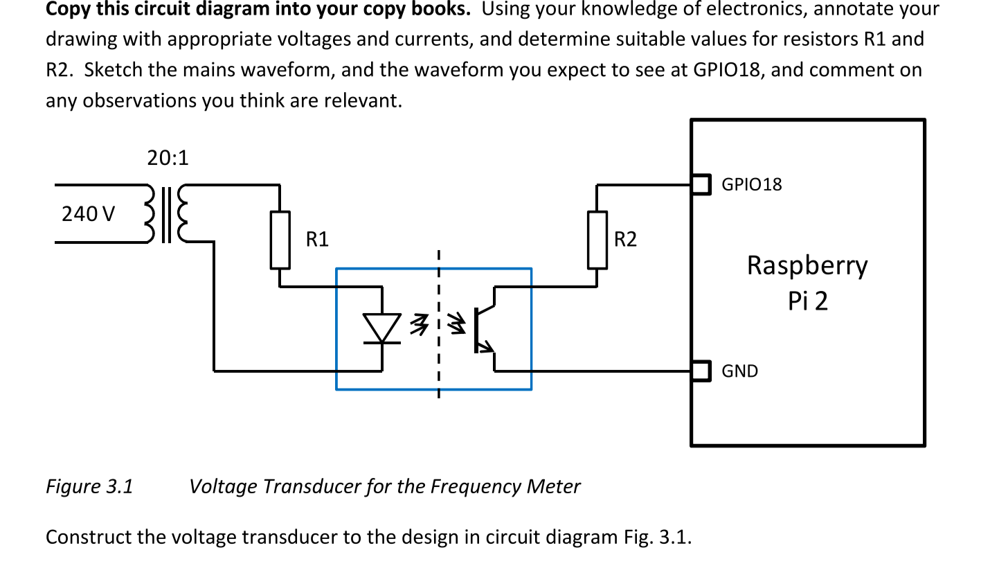
Well, the left part of the circuit mostly is stepping down mains voltage with a ratio of 20:1, do the output to the coil should be 12v, this then goes through the resistor which which reduces the current flow to the LED. You can work out what resistor you need by using Voltage = Current * Resistance. You know the voltage, and you need to look up the max current for the LED you are using, but it is likely to be 20mA.
The component on the other side of the LED is a light sensitive transistor, I belive the one depicted allows current flow when there IS light.
To work out the correct resistance for R2, you need to know the max current for the transistor and the voltage given out by the pi gpio pins, then use the sane formula as earlier.
I how this helps
Since we know the ratio of the turns, we can use the formula E1/E2 = T2/T1,
=> Substituting the values = 240/E2=20/1
=> Simplifying = E2 = 120v
so the voltage breakdown at the resistor is 120v
Not exactly sure if this is right or wrong, and it still doesn't answer your question, but this is what i came up with.
Actually it's 12V, not 120V...
Oops :p
No, the output voltage from the coil isn't 120v . The coil ratio is the same as the voltage ratio. So for this case. For every 20 turns (volts) on the input, you have one turn (volt) on the output. So the output voltage is 1/20 of the input
The basics, 240v stepped down to 12v ac, is being fed through and rectified by the optical coupler. So you have only the positive going part of the waveform going in. The optical coupler will conducting for this period, so depending on how GPIO 18 is set it, it's logic level will drop as the ac peaks.
You essentially have the LED in the optical coupler acting like a half wave rectifier.
You have 12v RMS at the output of the transformer, which will peak at about 8.5v on the positive cycle.
LEDs typically drop about 3v, so this leaves about 5.5v across R1. Assuming you want to feed the LED max 20mA, the value of R1 should be about 270ohm.
GPIO 18 should have the internal pull-down resistor enabled in software, so a current limiting resistor that suits the optical isolator should be fine. The GPIOs output 3.3v, so 1k should be ok? It is only there to stop draining too much current from the GPIO port and burning something out.