Takee green PCBs, use side emitting warm white LEDs and a few red normal LEDs and you are golden.
I usually use OSHpark which makes purple PCBs, but maybe some careful masking and some spraypaint would work?
OH SHIT make the silkscreen look like snow!
1 Like
To the other tinkerers:
Why do you buy 10 fuses when you blow the one in your multimeter?
Because you will blow it twice to make sure you really had the wrong probe points.
2 Likes
4 - Illuminated Base
My dad did finished the base for me. It came out amazing!
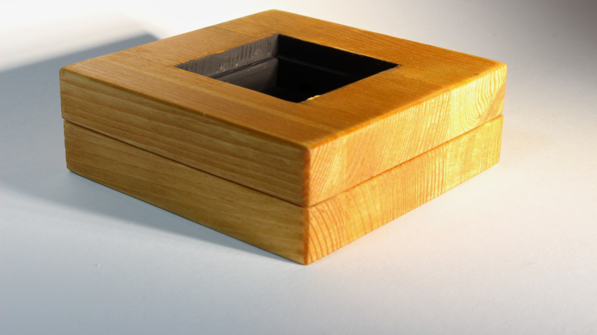
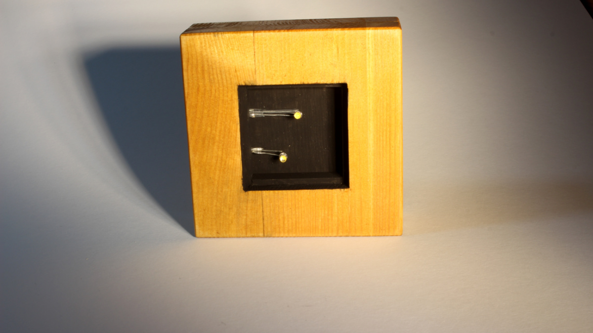
Screwed in the electronics:

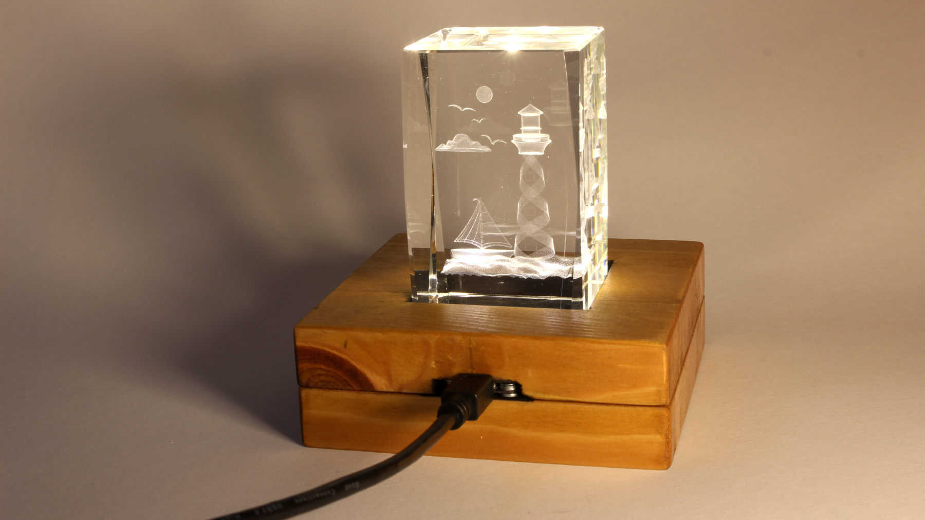
All pieces together:
DONE!
9 Likes
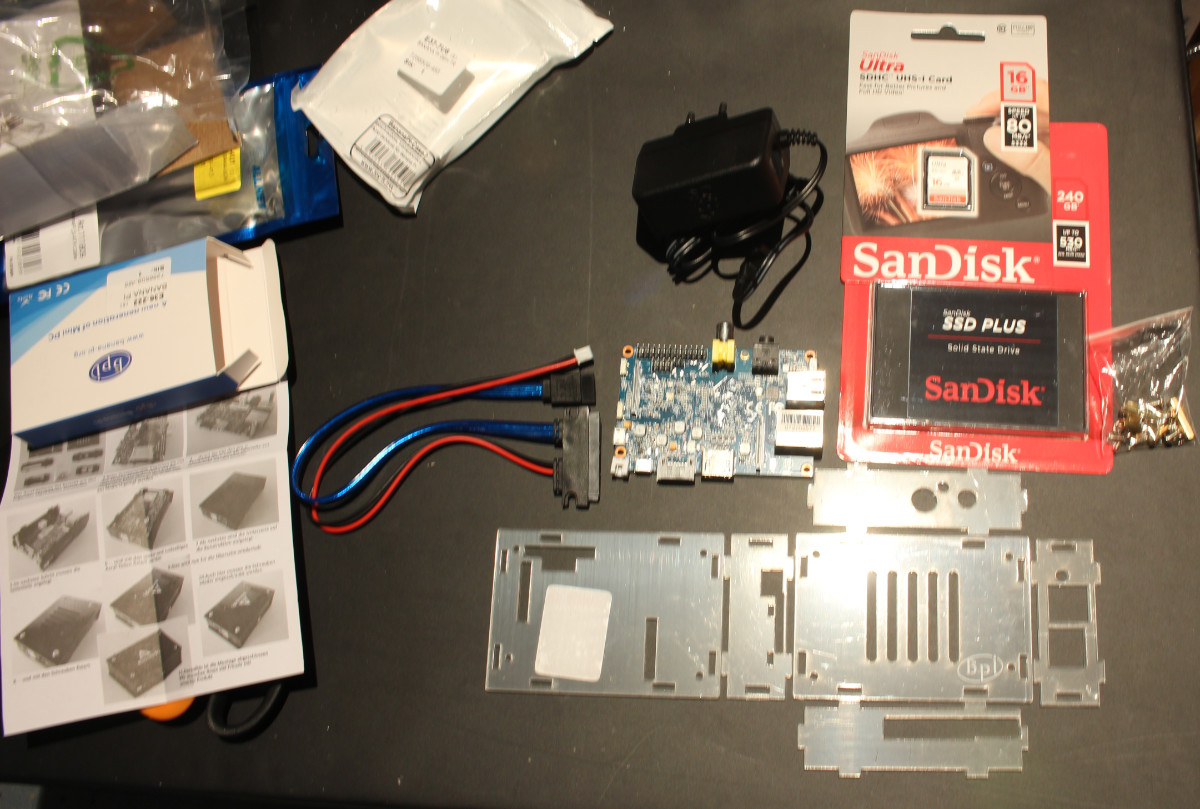
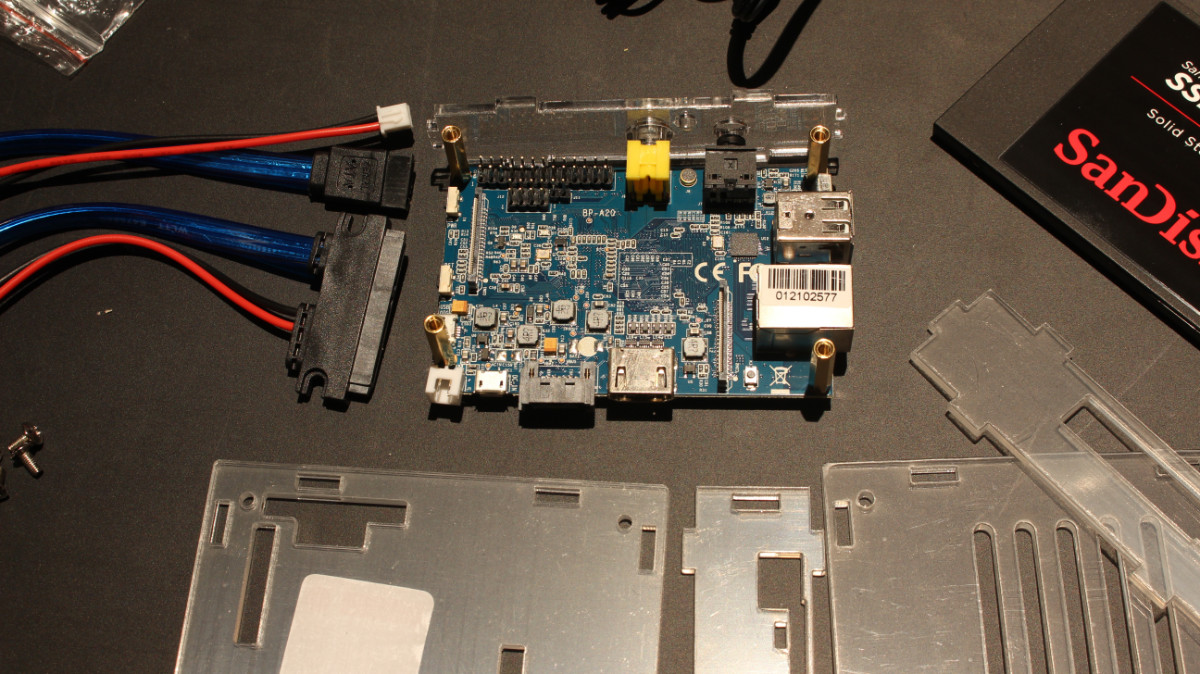
3 - BananaPi SSD NAS
…has been up and running for a while now. OpenMediaVault was painless to setup and use.
All bits:
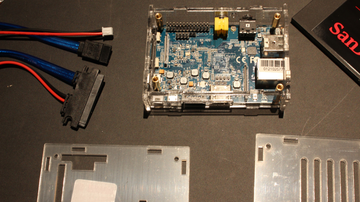
First side:
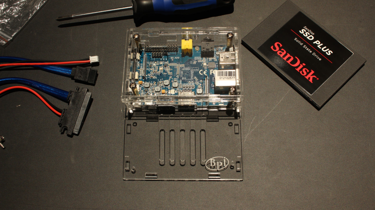
The other 3 Sides:
Base attached:
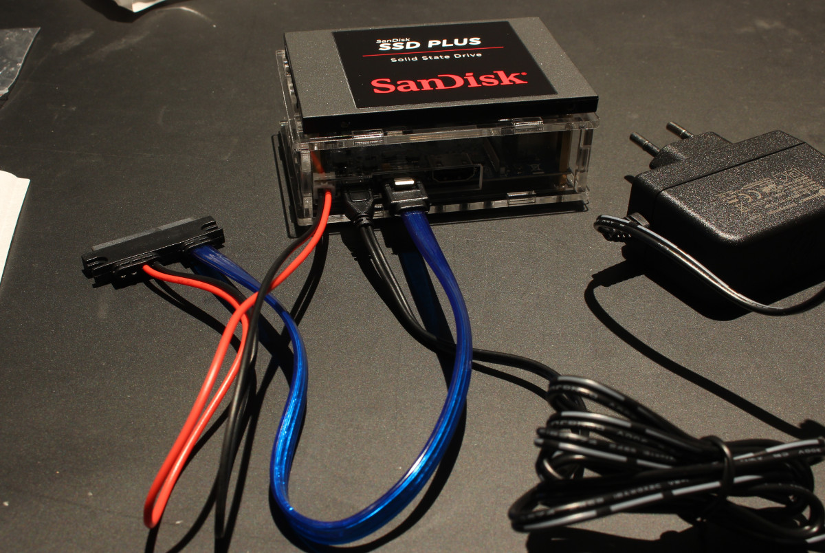
Cables plugged in:
3 Likes
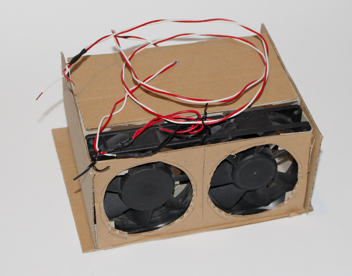
Project Fume extractor
I have this horrible bodge of a fume mover. Consisting of two small fans salvaged from old PSUs and taking up my bench PSU for power.
Yes, hotglue was involved in the making…
The Plan
Build a box with a fan and ways to support activated-coal filters, put a switch on it and boom.
Considerations:
- Switch on the device so I don’t have to unplug it from the wall
- Dust Filters to reduce dust flying arround while having it running
- optional: proper hookup for a dryer hose

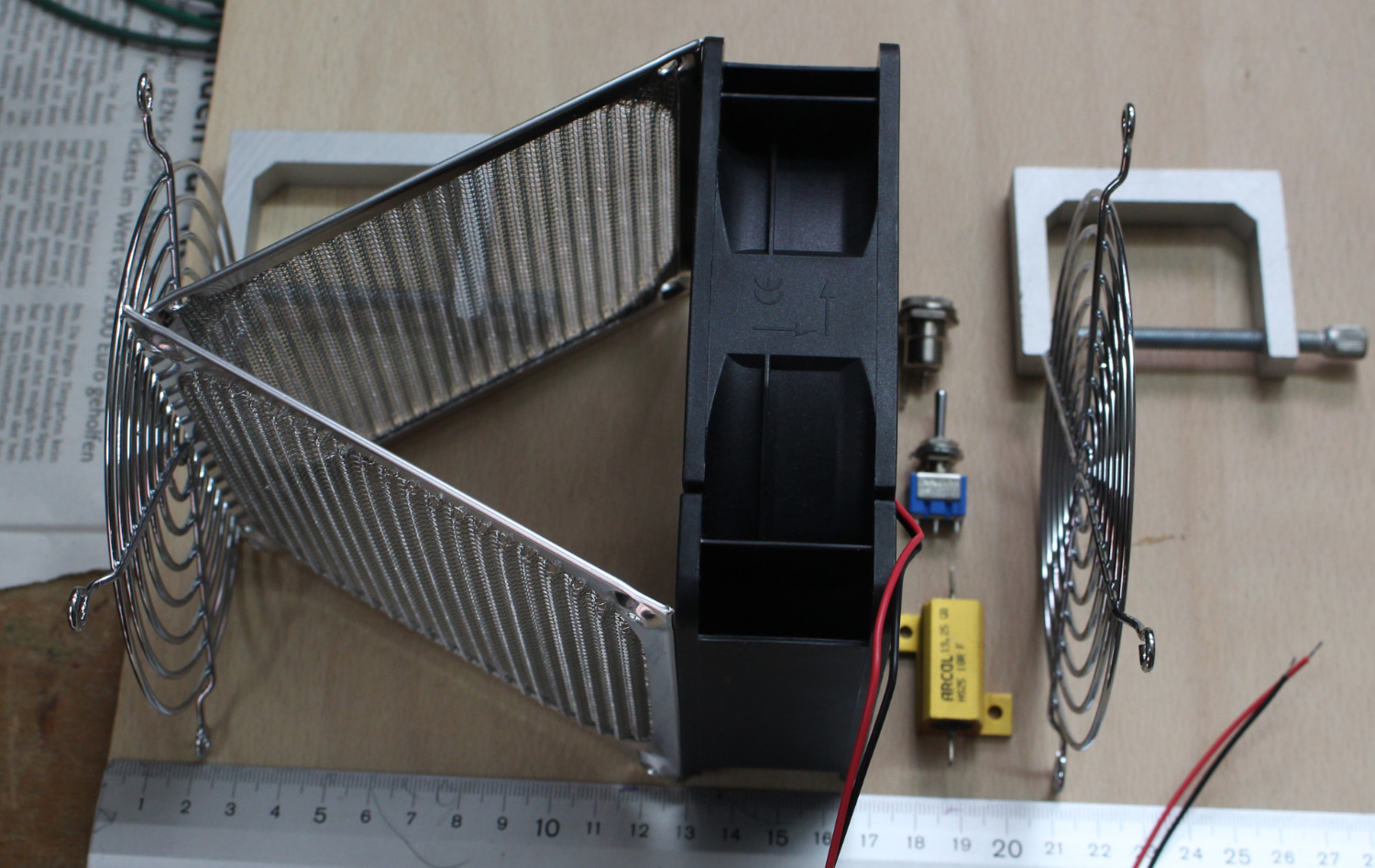
Labels are in German, you should be able to figure out what is what.
Parts:
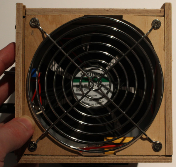
- Sunon MEC0381V1-0 (10W Mag-Lev fan)
- Vibrattion dampener
- 2x Dust filters (they will be as a V in the air stream)
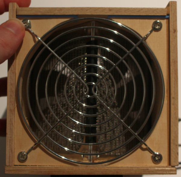
- 2x fan grills (the fan is somewhat evil)
- 12V wall adapter
- 18 Ohm resistor (the golden chunky boy)
- barrel plug
- 3-Position switch (either the resistor is in series with the fan, or not, or off)

6 Likes
Project Fume Extractor
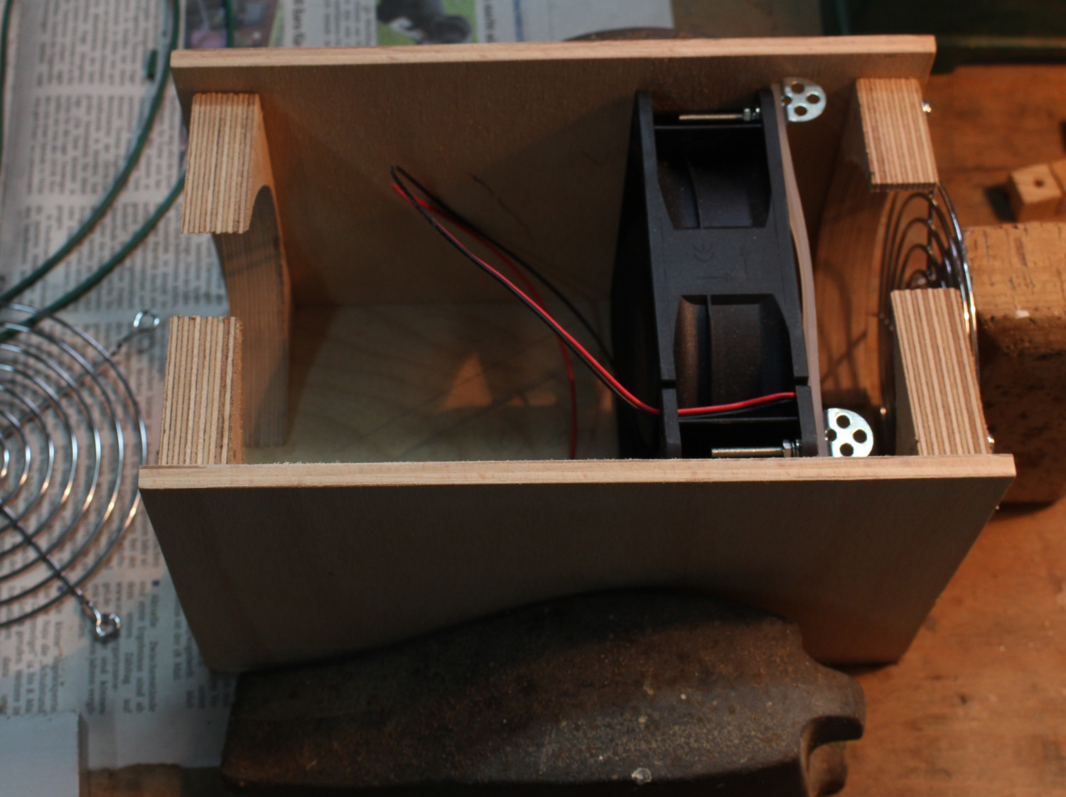
Plan will have to change a bit due to the fact you can not put a screwdriver trough a wood block. I will probably moce the electronics into a small box that will also function as a grip above the main compartment.
I also took some video (somewhat noisy):

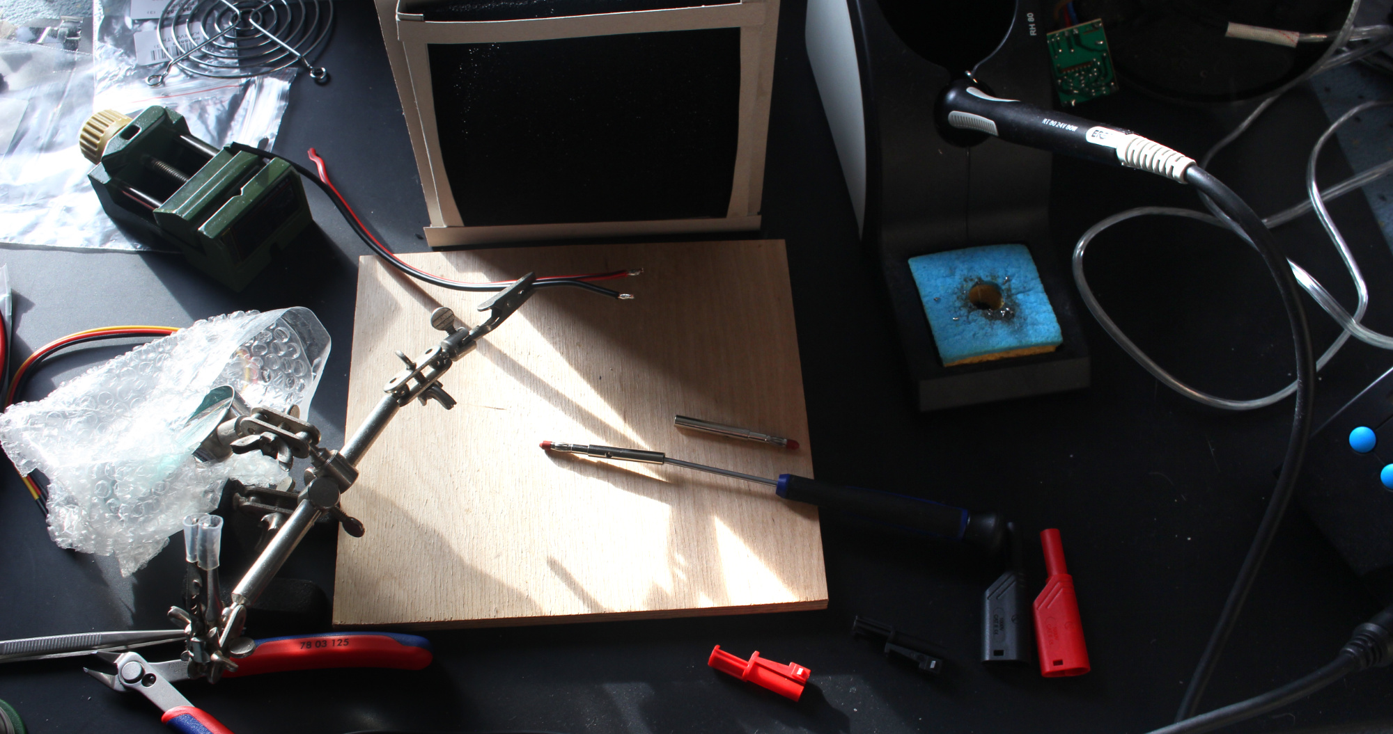
Physical design considerations (self doubt)
“Yes this works”
Soldering the components. The switch will either put the resistor (which is oversized as fuck) in series with the fan, or not).
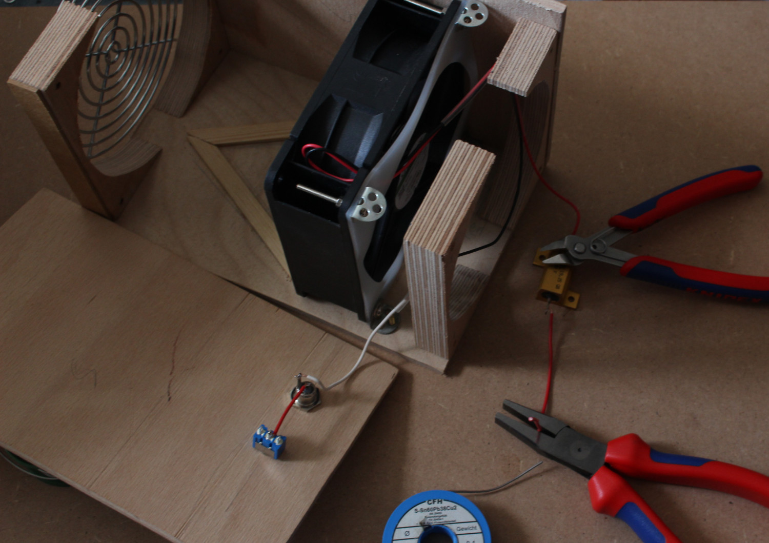
Done!
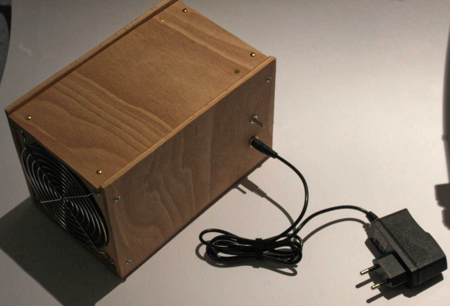
Inlet and Outlet side by side:
7 Likes
Updated above post.
This thing moves a lot of air.
On “low” it runs at 50 ish dB©, high is almost 70 dB© and moves a TON of air.
The fan can actually hold the filters stacked against it’s inlet when running full tilt. So having double the area was a good decision.
Edit 2:
Took some measurements:
Resistor gets to 40-ish °C during extended operation. “Low” mode is 4W to the fan, “high” is the full 10W (or 9.6 as measured).
Works amazingly well for solder fume remover, also works to circulate some air through the room.
2 Likes
I am just going to keep this going.
This here is to improve the cooling-bodge I have on my DIY-audio rack. Currently it is a 3rd Hand holding an old PC fan I had on hand, random wires stuck into the Tamyia-Output of a simple racing pack charger (as in: it is a constant current supply, 11.2V DC Powerbrick).
The goal of the adapter cable:
- Not short out the powerbrick
- Allow for monitoring of voltage or feeding from my bench PSU
- Be useable to check fan headers on mainboards
With that said, I present the parts:
To hook up the lab-connectors, I just used som speaker cable I had on hand.
There is a small grubscrew in the contact pin, just wind that back and stick the wire in.
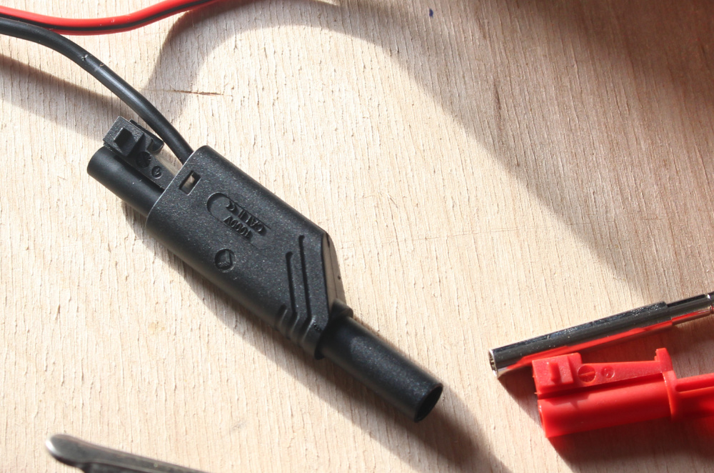
Slide the plastic bit on.
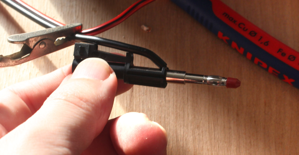
Then stick it into the caseing.
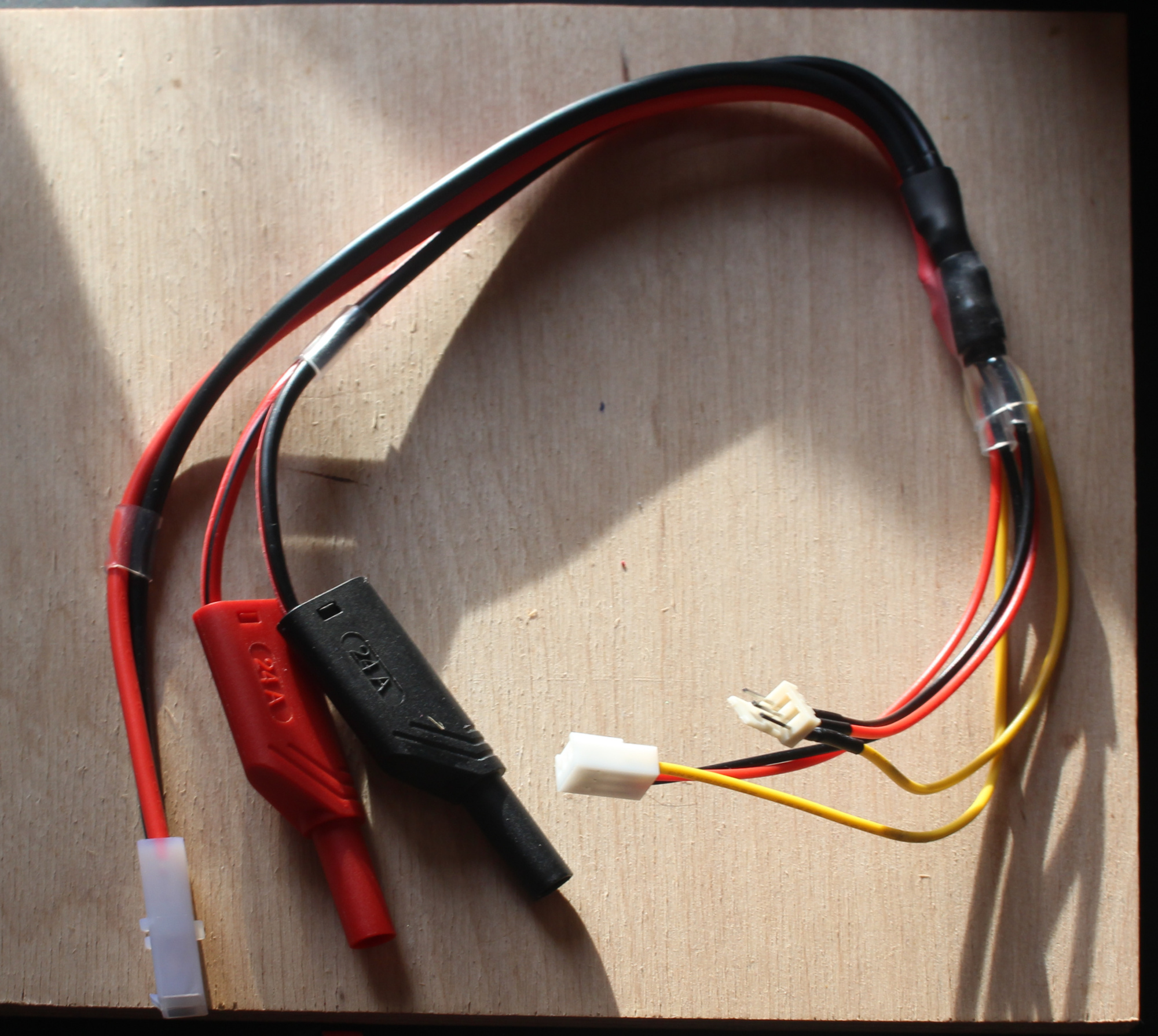
I cut the power part of the fan extension, soldered that to the lab and Tamyia connectors and done!
Came out better than expected but worse than it could be.
2 Likes
If you order stuff like the tiny85 from a jameco.com or lcsc.com (if you can wait on the shipping from china) you can get them significantly cheaper and without the pesky board: https://www.jameco.com/z/ATTINY85-20PU-Atmel-Microchip--ATtiny85-Microcontroller-8-Pin-PDIP_2151312.html

Pardon me, but how is this relevant to this thread?
I genuinely thought this was spam.
1 Like
DIY Lighting overhaul
Am currently looking at the parts I have for my DIY lighting.
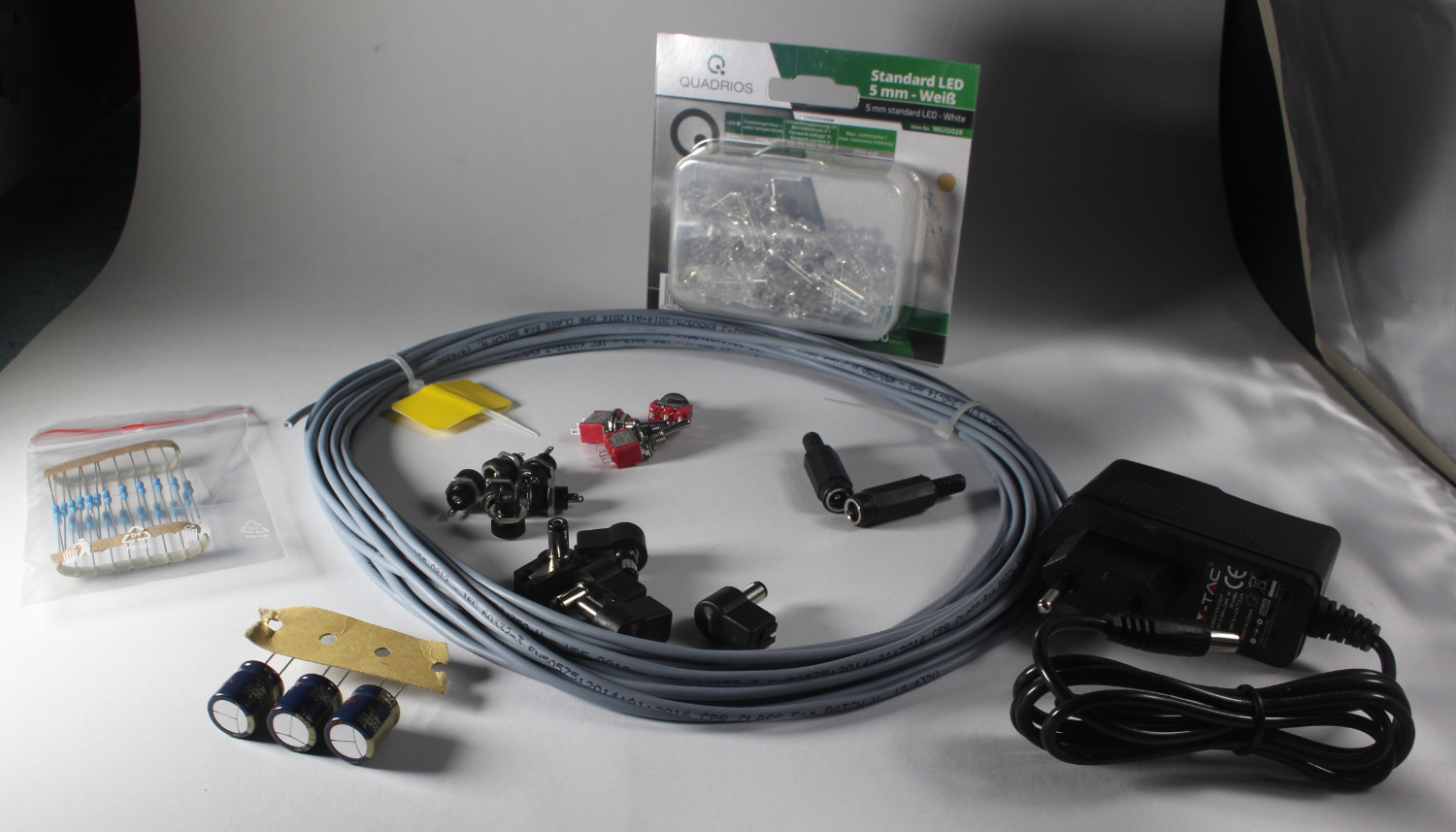
I now also have the L-profiles to put the LEDs into.
Plan looks like this:
Have two barrel sockets so I can feed power through, then a switch followed by a capacitor for smoothing.
And then there is the 7 groups of 3 LEDs. Fed from a 12V PSU (because they are common and cheap).
Anyone here using Ledcalc.com whenever you need to figure out the resistor value before the LED? Here is how to do it manually:
Us = 12V ← Voltage from the PSU
Uf = 3V ← Voltage drop per LED
Ur = ? ← Voltage to apply Ohm’s law to
If = 16mA ← will still be spotlights
x = 3 ← Number of LEDs in series
R = ? ← The Resistance you are looking for
The magical formulas:
Ur = Us - (x* Uf)
R = {Ur \over If}
Replace Ur with the formula and get:
R = {Us - (x* Uf) \over If}
Stick some values into it:
R = {(12V - (3* 3V)) \over 0.016A}
R = {(12V - 9V) \over 0.016A}
R = {3V \over 0.016A}
R = 187.5 {V \over A}
And instead of writing V \over A (not to be confused with VA), we write \Omega
R = 187.5 \Omega
187.5 Ohm is not an easily available resistance, so just use the next step up (220 Ohm) for 13.6mA current through your LEDs.
Lastly, you need to know how much power the resistor is going to see. 1/8 Watt is probably fine, to be sure:
?W = Ur * If
In my case, this is 41mW, or a 3rd of the load a 1/8W resistor can take.
Lastly, the drawing of what I intend to build:
The LEDs in the group should be so close I can just solder one leg to the next, not sure what I am going to do to link the groups.

4 Likes
DIY Ligthing
Sanity check:
(yes those are 3 LEDs on the breadboard)
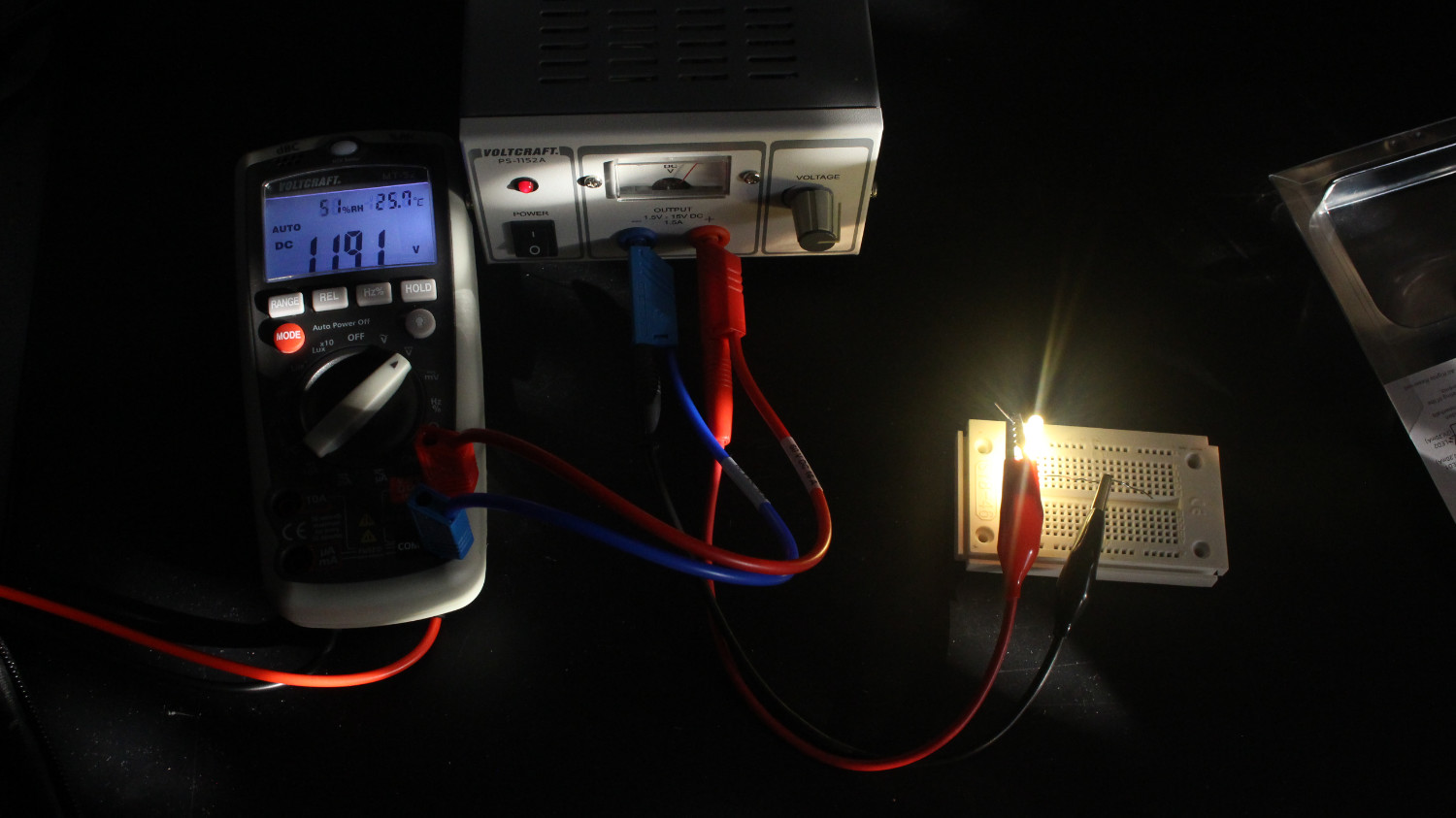
Holes drilled (all 21 for the LEDs, the 2 for the barrel sockets, the switch and 2 for the rivets)

Sanity check No 2

I call this image:
I realy should have a bench
Also: Soldering done

And done!
Only took two hours start to finish. As I did not set my soldering station to 3x, I will have to make the other two later…
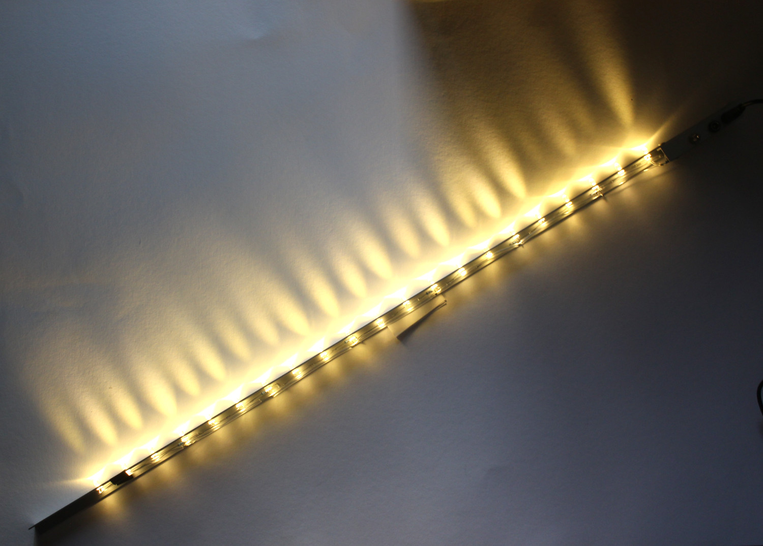
It does not look bright in the photo, but this is 4W (I think), and I kind of regret not giving the LEDs less current.
This is it installed. Now my displayed items shelf has nice warm, almost jank-free lighting.

6 Likes
non-techy suggestion here, diffuse the light on those LEDs, photography and blender have taught me harsh light is no bueno
3 Likes
Good suggestion, I have no idea how to put this into practice.
Sanded plexi? Like 600 or 800 grit.
4 Likes
i agree on plexi. Is a common trick also used to “bend” light, and even without sanding could give enough diffusion to look good.
if you end up with issue managing the heat, mount the LED strip on a aluminum strip to act as heat sink, but i think your mounting has already enough spread
Should still have some arround, can try.
I don’t.
I run the LEDs at a conservative 16mA (see post 24), the voltage drop per LED is in spec and they don’t get fed any funky waveforms.
Why would I mount the Aluminium L-Profile on more aluminium?
1 Like
Try without sanding first, to see if you need to sand it.
1 Like