Just remembered seeing this thing, and it appears to be thin ITX. Two different AMD Ryzen embedded APU’s to choose from with a built in Arduino:
Also, as far as getting the standoffs level, there are a few options. On one case I stuffed a board into an old VCR and the bottom was uneven with different levels to it. I started at the highest spot and put a standoff through a penny and glued it down, then proceeded to do the same with the rest. I just stacked up pennies and glued as needed to get the height adjusted. I used some extensions for some of the rear coastline I/O and didn’t need to get that lined up. You might be able to get some aluminum machined to thickness and epoxy it in place as a better solution.
I’m sure there are a few ways of going about it where you get something to the right thickness and glue or epoxy it down. Possibly even a thin tray to mount the board on that has just the right thickness and can be slid in and screwed or latched down.
That thing looks really cool. Might have to watch it. Putting it in one of these cases may be overkill cooling-wise, though. But there are some really nice (much smaller) thin itx cases that would work good. Just a super tiny yet relatively powerful computer.
My idea was to use like an arduino uno and use that in addition to a regular thin itx based system. I found a socket 1151 thin itx board, so I could do a skylake / kaby lake based system for the second case if I wanted to. I’m going to see how this works with the board and processor I have now, though.
Been a while, but I heard back from the metal shop this morning. The guy working on my cases has been very busy with other projects and hasn’t had much time to work on them. He’s enlisting the help from someone else in the shop and is hoping to get everything done by week’s end.
Sooo… Maybe this weekend I’ll get them back and start fitment and mounting of the motherboard. If that goes well, maybe I’ll get the water cooling sort of mocked up and functional. If that goes well, maybe I’ll try to ceracoat them.
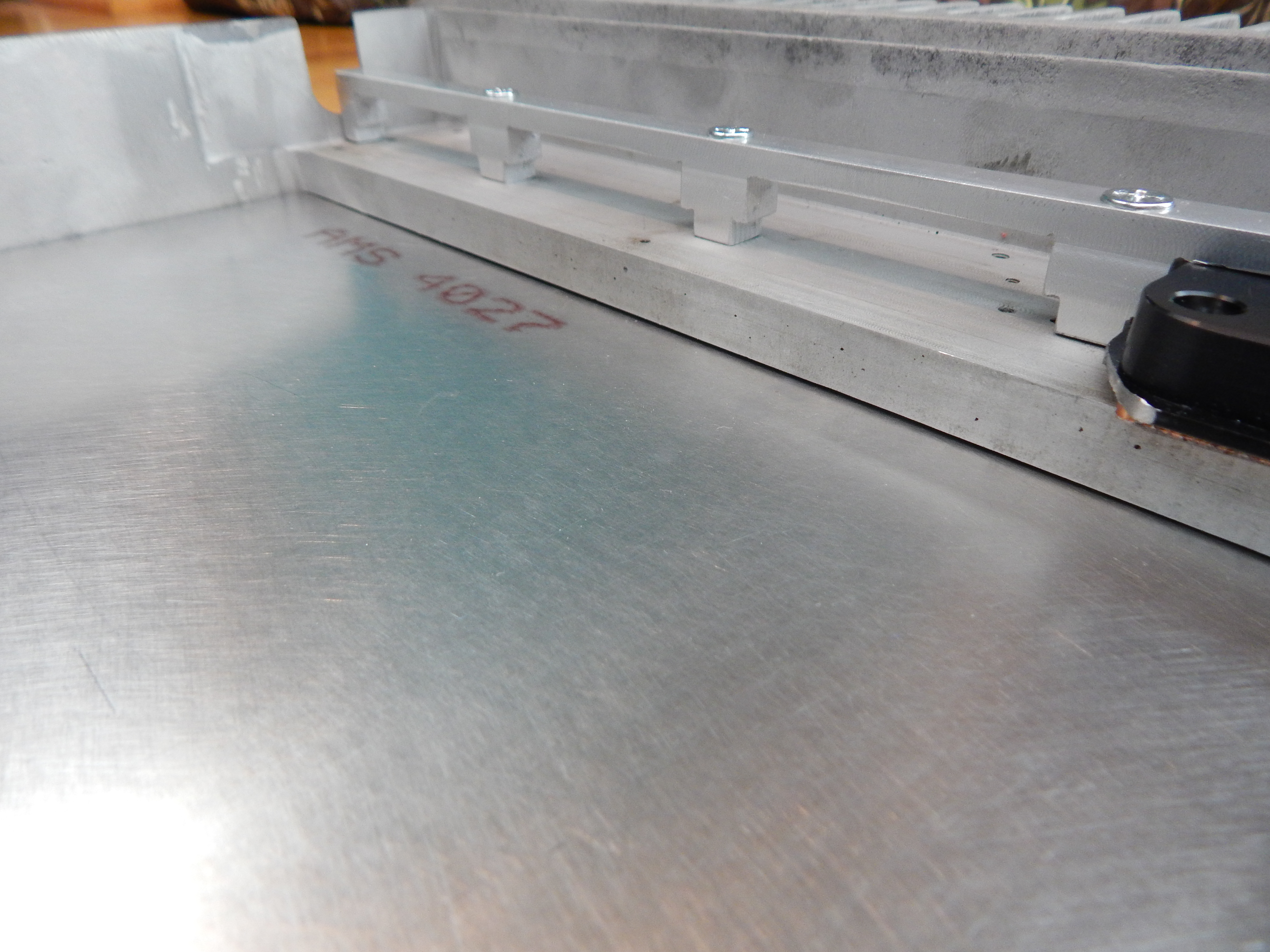
I kinda figured I’d have to do some more modding and fiddling. I don’t know if a jigsaw will do it, and I was sort of hoping to avoid the router/endmill nonsense. I also need to smooth that area.
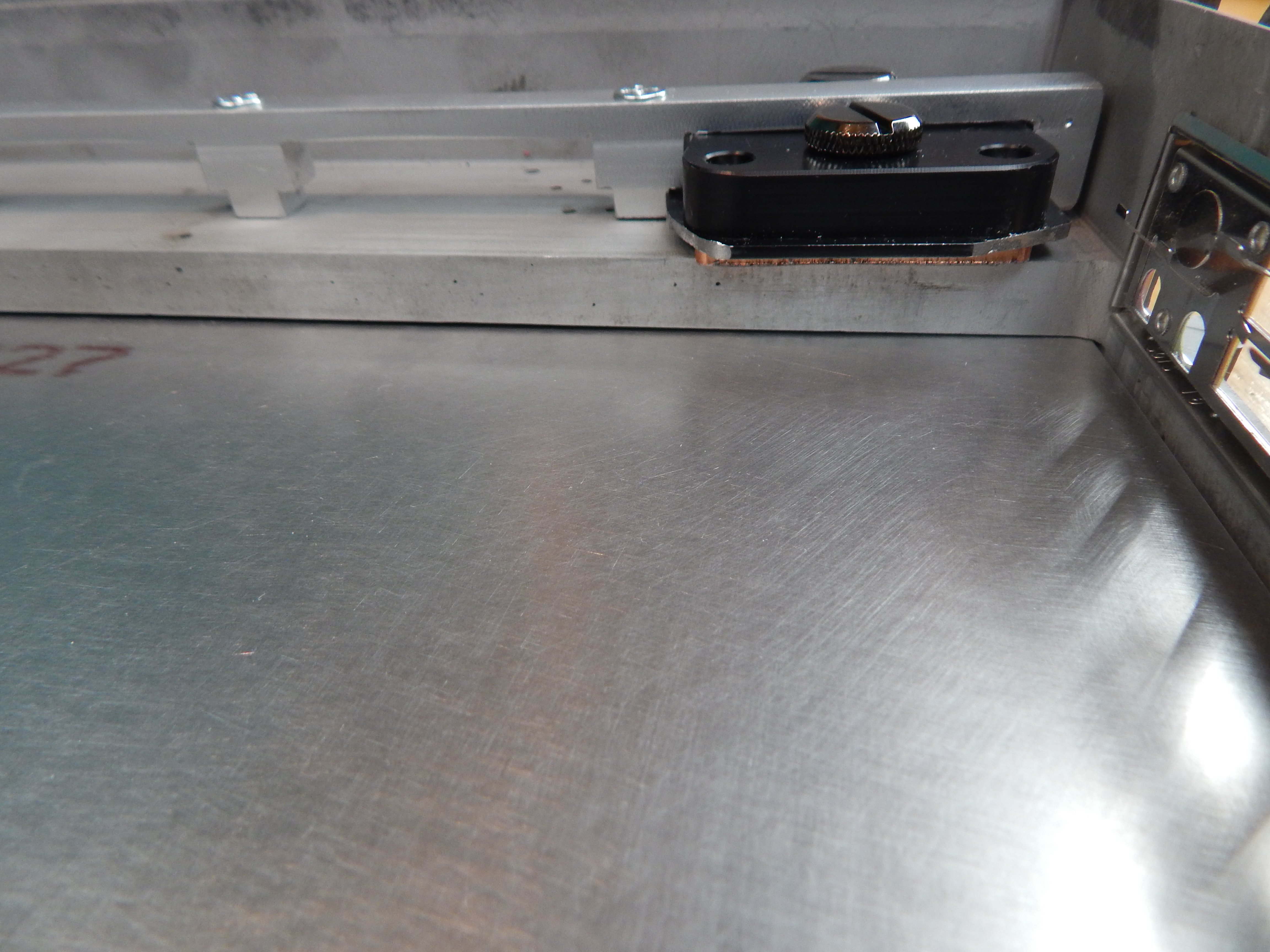
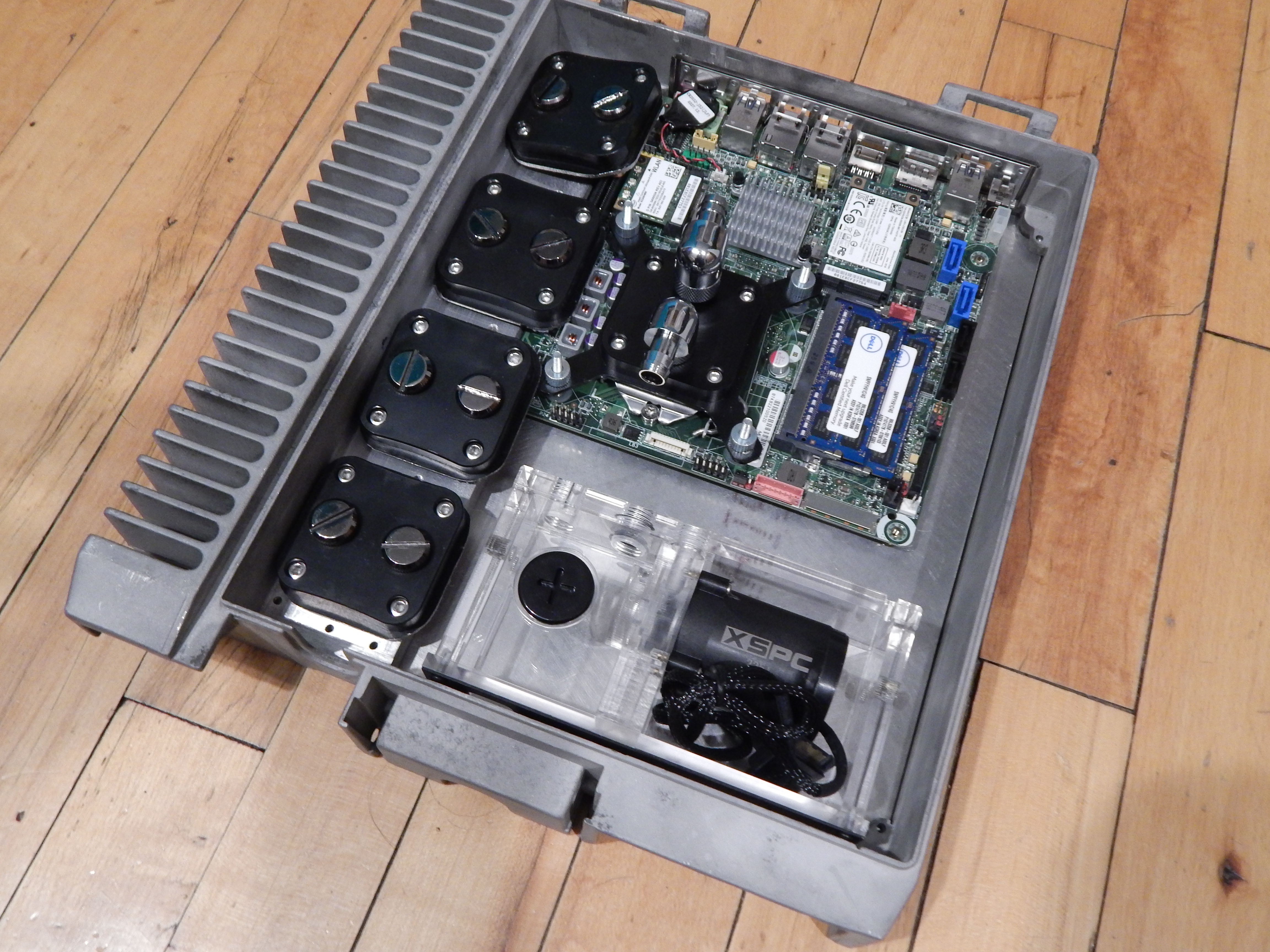
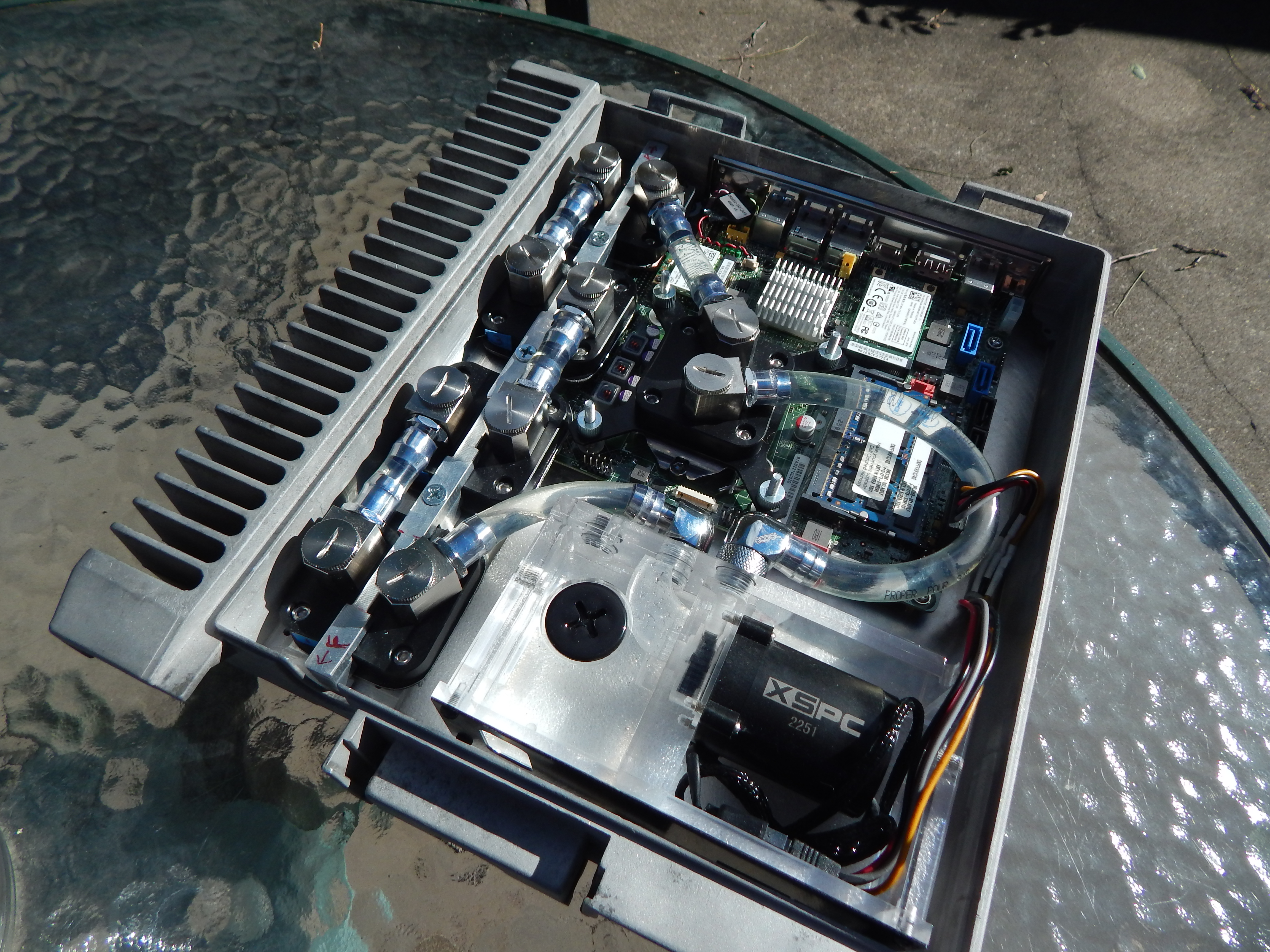
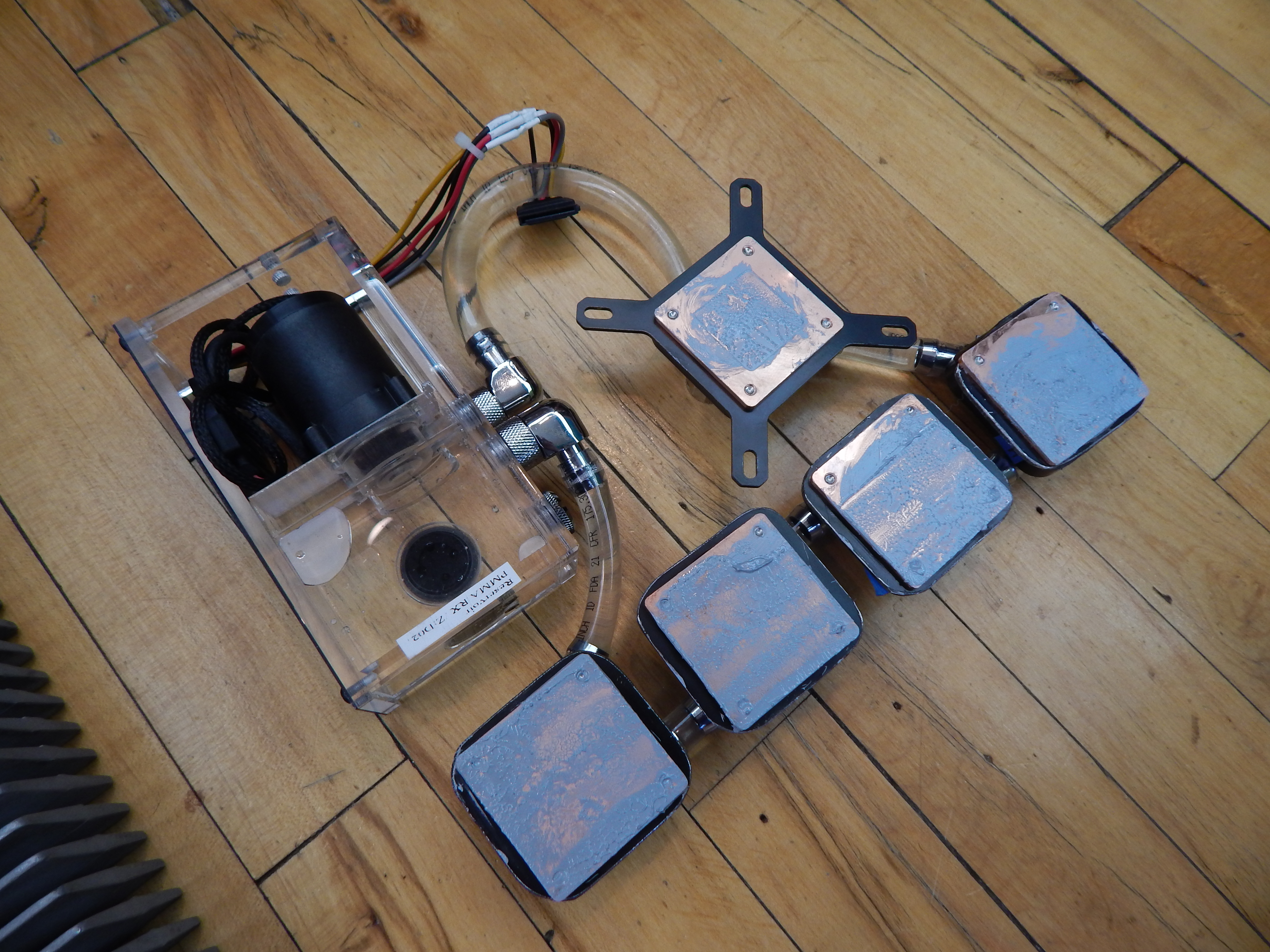
I really hope the two water blocks towards the rear will fit once the motherboard is in place. The brackets they made are cool, and allow me to have four water blocks in total. I might have to live with two if there isn’t enough room.
Also, I need low profile fittings for the water blocks. The lid doesn’t fit. Either that, or I need to figure out a different water block solution.
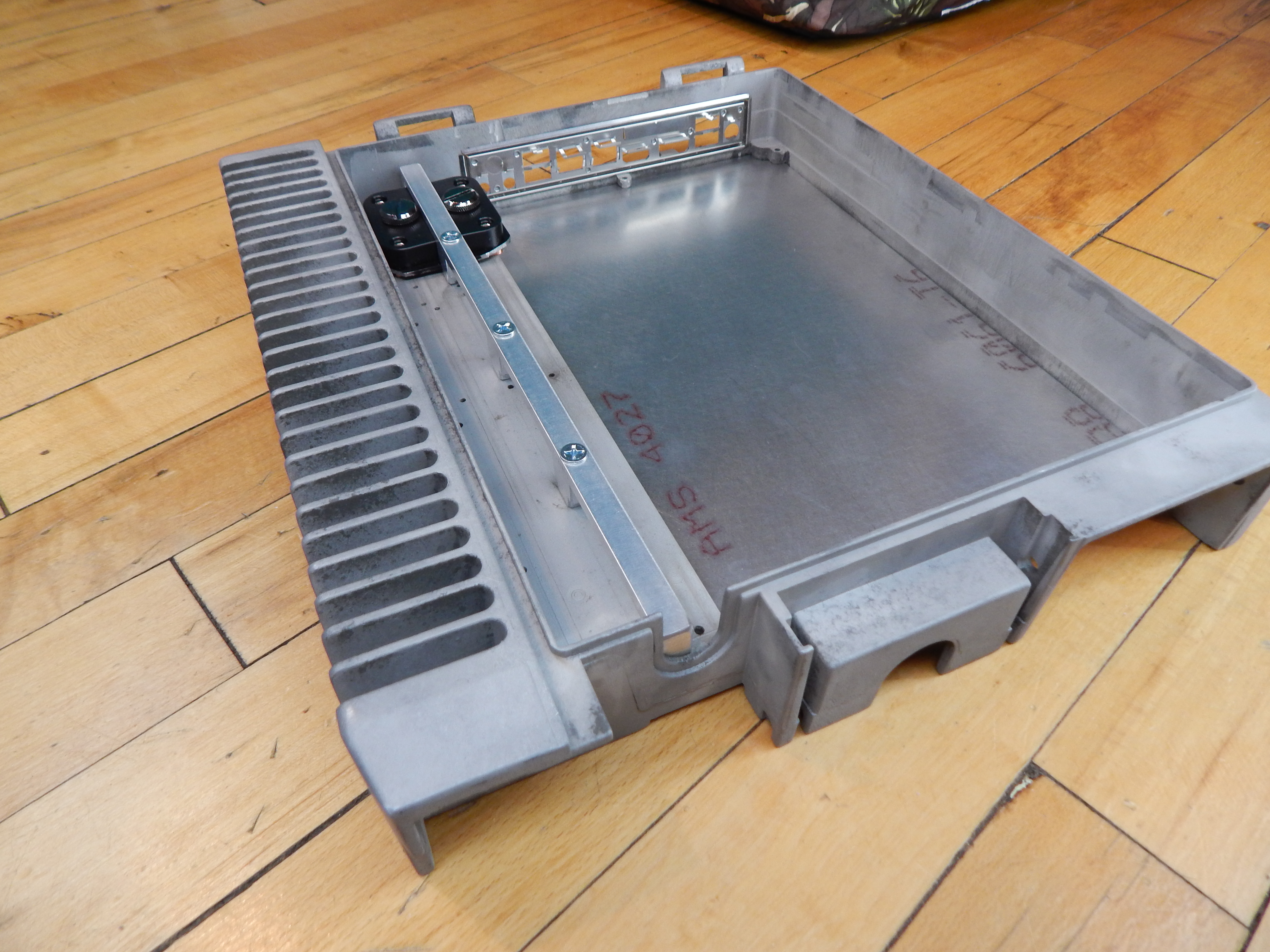
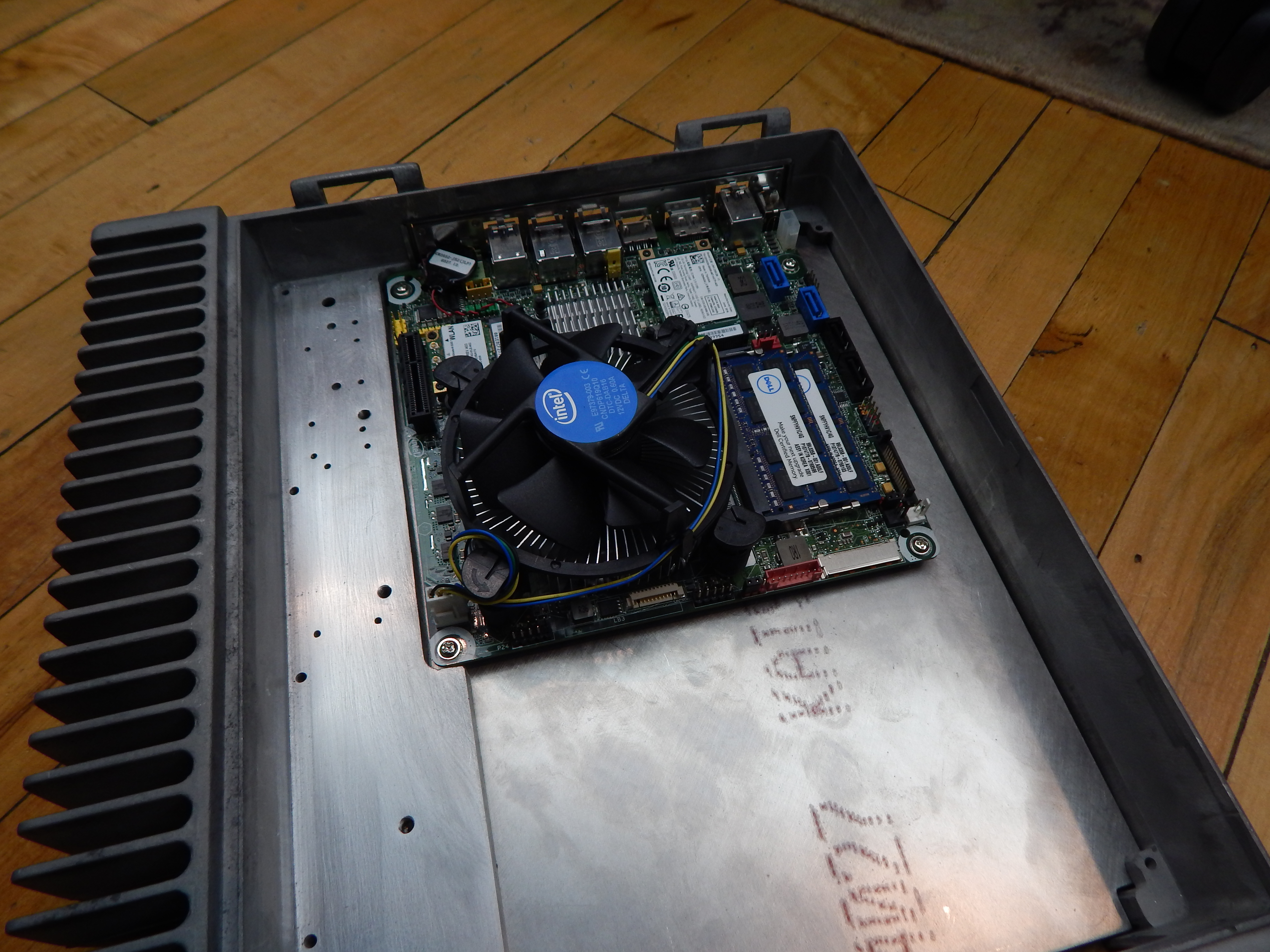
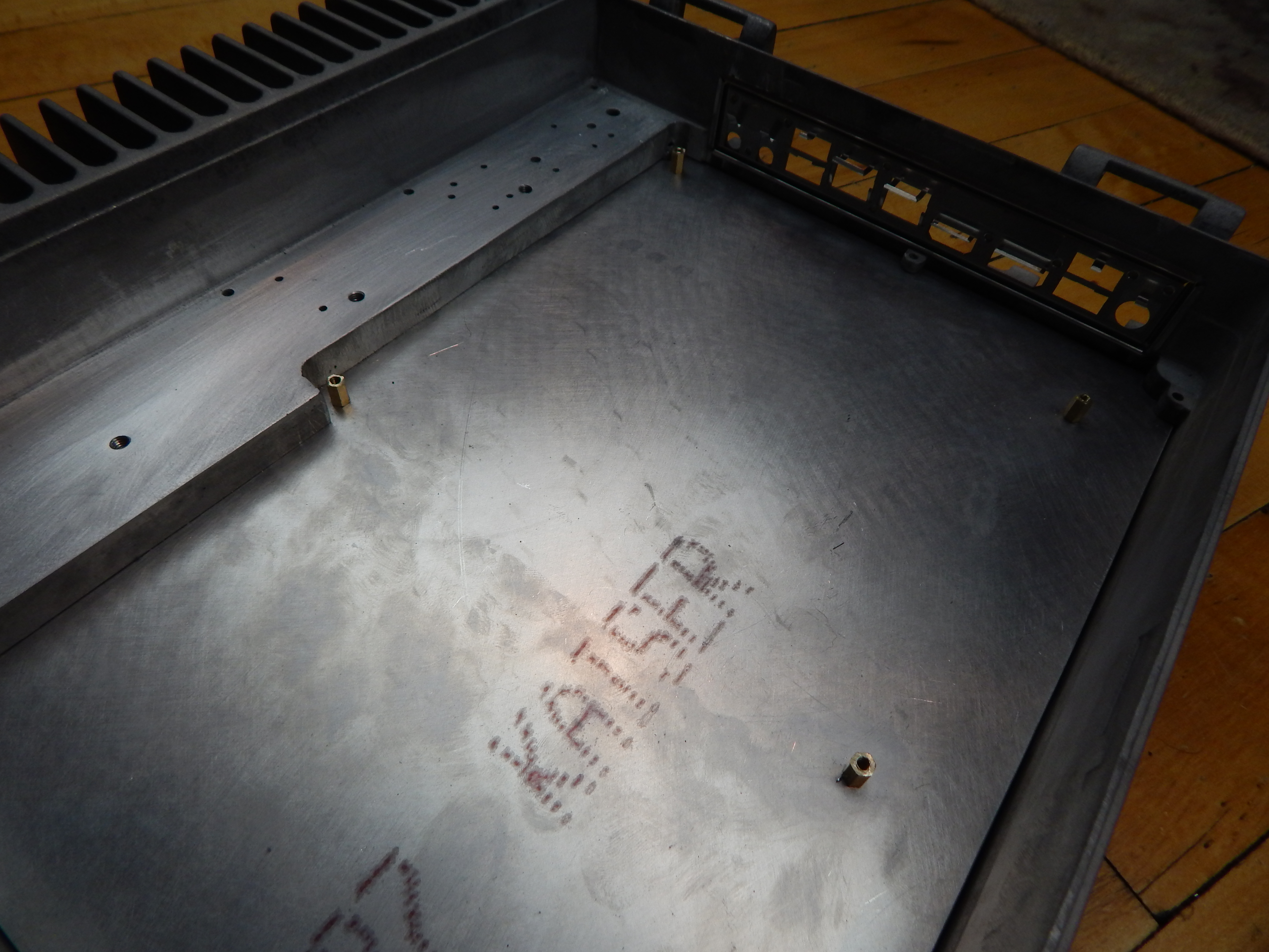
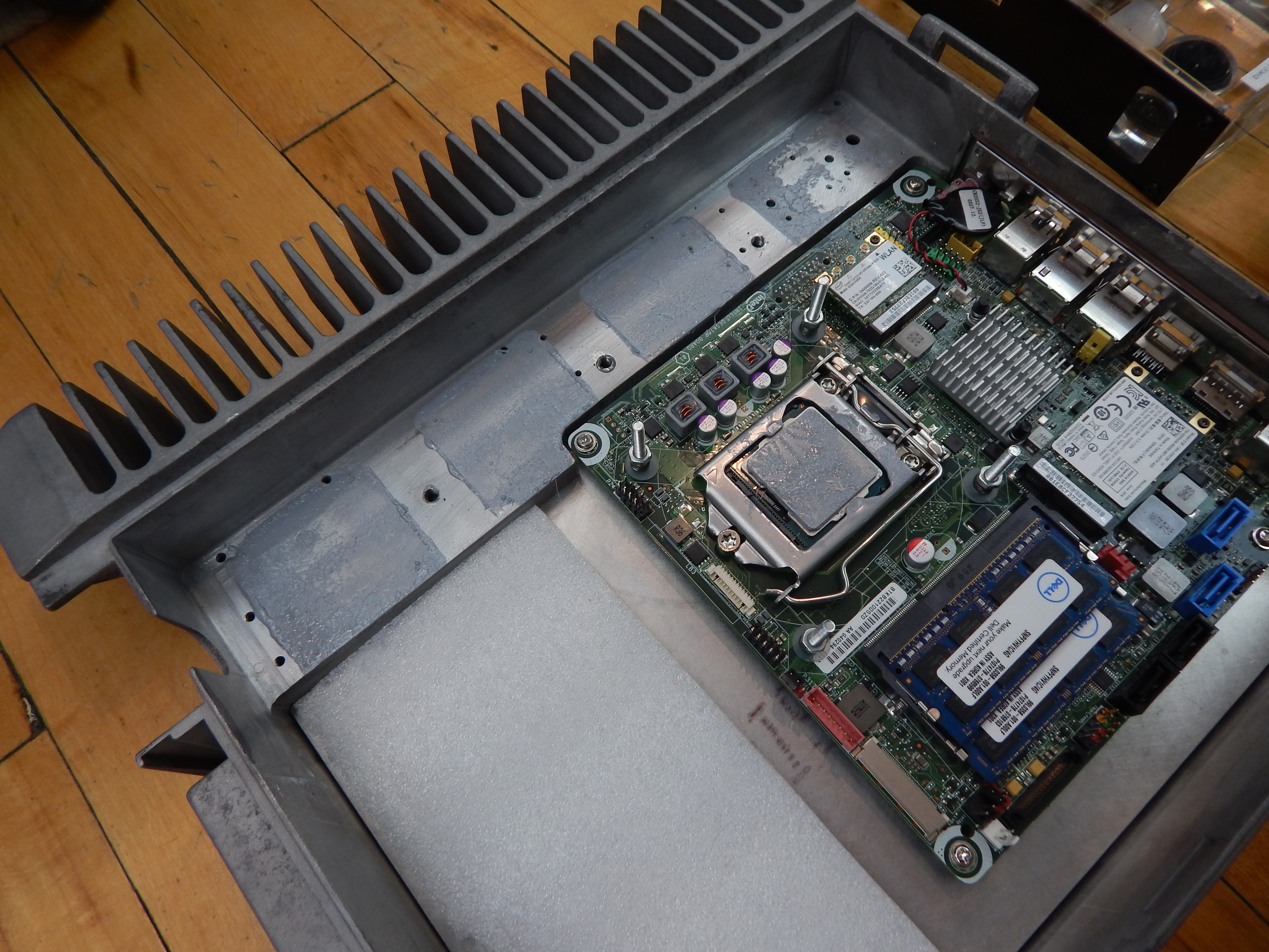
Got the case notched for the motherboard, and the standoffs installed. The motherboard fits quite nice, but I had to shave the standoffs down a bit. They were 10mm tall, and I ground them down to about 8mm. I might take four more and try to get them all at about 9mm, as the motherboard sits just a smidge too low.
Now I’m off to do some modifications to the water blocks, just clean up the metal mounting brackets.
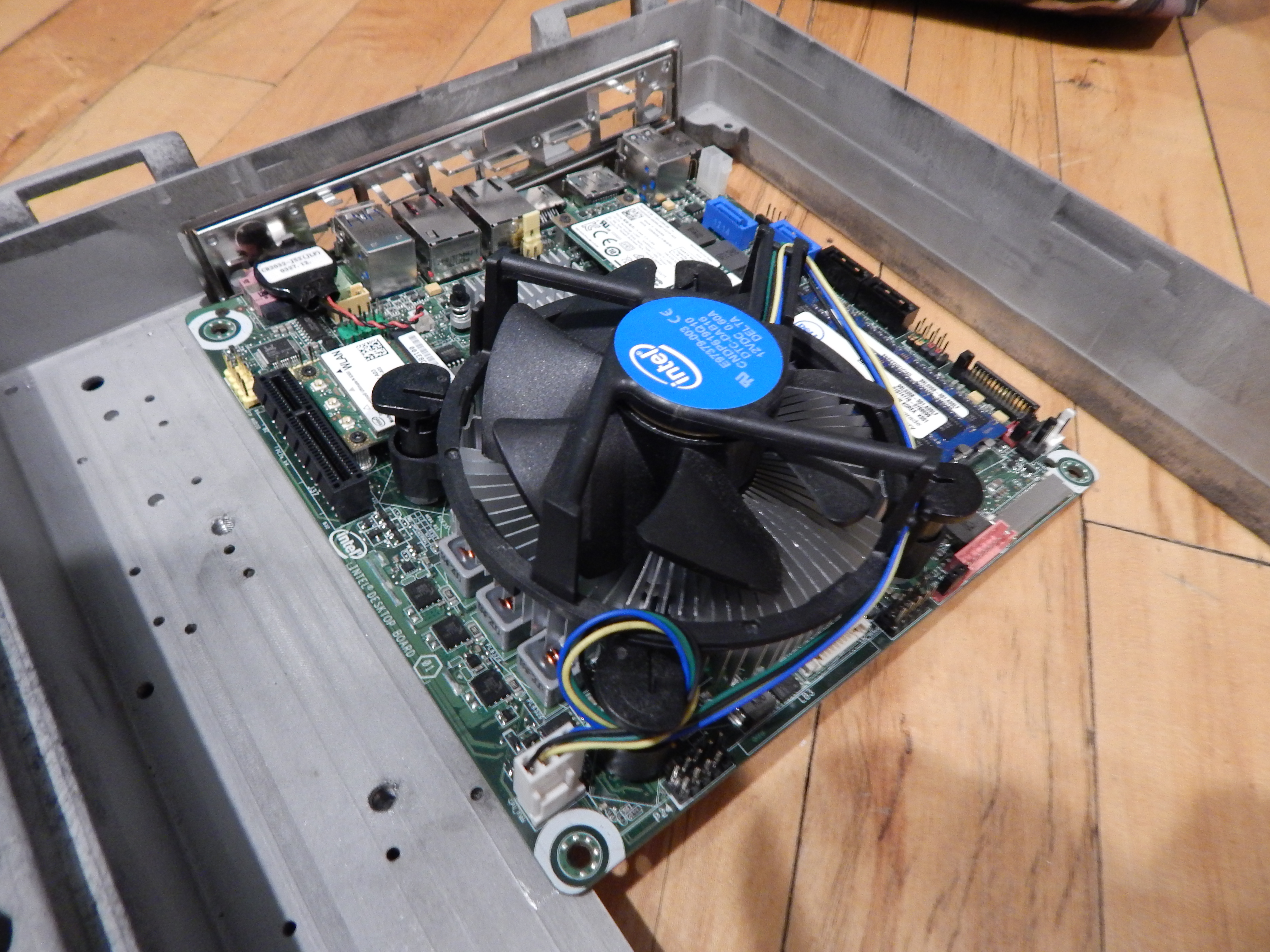
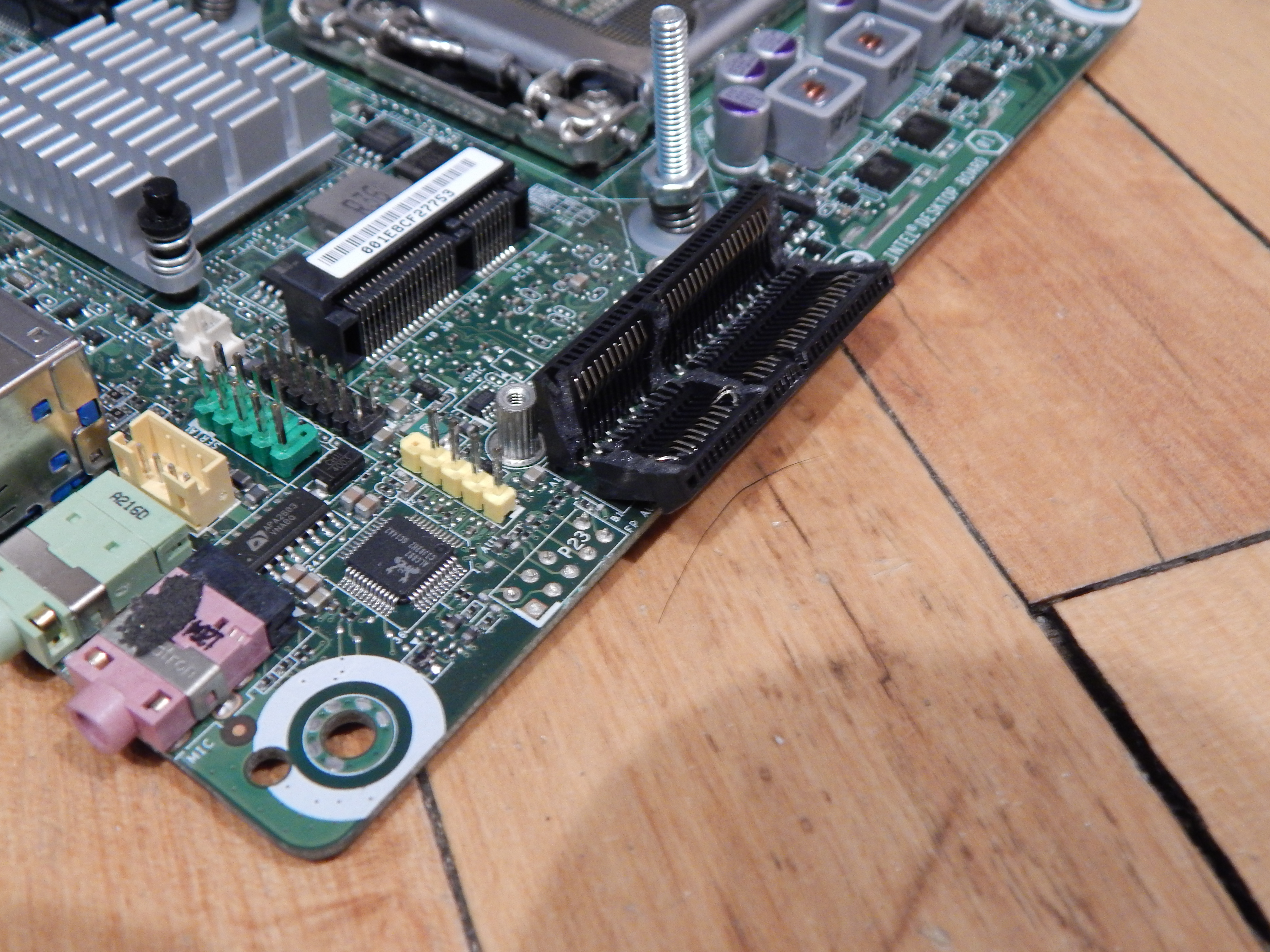
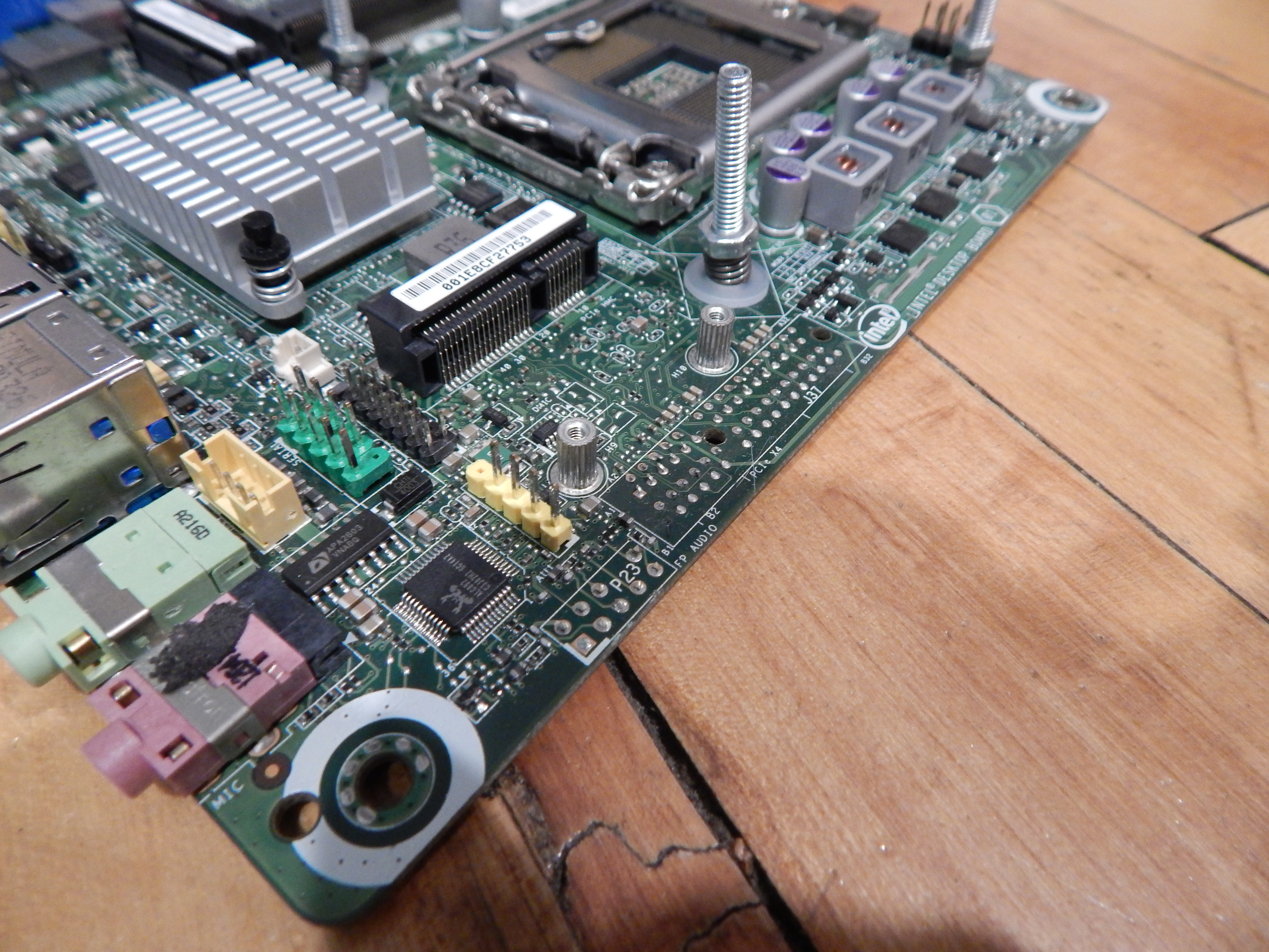
I am pretty positive I can fit two in there. Three may be possible, but the CPU fan header might be in the way. The fourth one, at the back of the case, won’t fit because of the PCI-e slot and front panel audio header. If I was real ballsy I could remove all of those things and I think all four would fit with no problem.
The two rear water blocks don’t fit at all, because of the PCI-e connector and the front panel audio header like it thought would happen. The second one is held up by the CPU fan header. The front one fits fine.
So, anyone know if there’s any danger to removing the PCI-e connector off the board? I know motherboard’s are many layer designs, so would attempting to remove the connector cause damage to other things? Same for the fan and audio headers.
According to the spec sheet they will be 19.5mm tall when installed. I have between 18.5mm and 19.5mm of space off the top of the water block. It’s hard to measure with the top on. It’ll be very tight. I might order two and see if they work.
Somehow I didn’t order enough of the fittings I have now, which is good as I can’t use them anyway. I probably have enough between the 90s and the straight barbs to at least get this going and tested, though. Won’t look pretty, but it’ll prove whether or not this will even work.
Well, it definitely works. Three of the water blocks transfer enough heat to keep the CPU at about 30c idle and between 40c and 50c under load. I let the stress test go for about 45 minutes before I had to stop it to go do something else. Didn’t want to leave it alone in case anything happened.
The large heatsink fins gradually warmed up and became quite hot, so the water blocks are transferring the heat. Only issue is the return line going into the reservoir was warm. The CPU temp was increasing pretty steadily. Not sure if I hit the maximum wattage that could be dissipated or what.
I’ll probably order some of the lower profile fittings I guess. Not looking forward to dropping a hundred bucks just on fittings. But it’ll be interesting to see if the fourth water block will help.
And finally, I am disappointed in the pump. It’s pretty loud, and if the res is in contact with the case in any way it becomes very loud. I will have to devise a way to mount it with some kind of rubber isolation.
I got the fittings installed. Woof, that was spendy. But it works, and the lid fits. It looks really cool, I’ll take some pictures and add them tomorrow when I have some natural light.
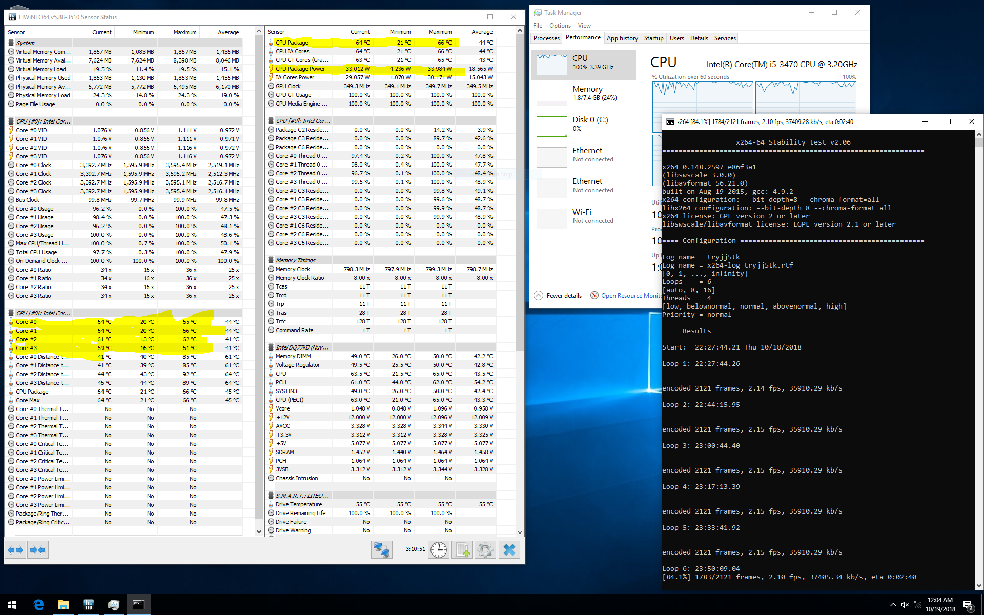
But, as evidenced by the screenshot above, the processor reached the mid 60s after an hour and a half of stressing. It may continue to climb, not sure. It sure feels like the heatsink fins can’t dissipate all the heat.
It seems like the board limits the power to a bit under 35 watts, as the processor has a 77 watt TDP, and I am using a 240 watt Dell power adapter. Unless that reading is wrong?
After I take some pictures tomorrow I will take everything out of the case again, probably not for the last time. I need to figure out how smooth/level the area the water blocks mount to, especially the rearmost/first in line one. I’ll try to take some pictures of the thermal compound spread when I take the loop out.
Speaking of thermal compound, boy am I going through it at a depressing rate. Lots of MX-4 going into this project.
Thanks guys. Pretty fun. Never water cooled before, so I’m enjoying learning. Already planning my next project, which I started here on the forums a year or so ago. Mac Pro case related.
I let it stress test for 13 or 14 hours overnight, and it stuck in the low 60s max. It peaked at like 67c. So that’s good.
So, yeah. To finish this: slightly taller standoffs (~9mm), smooth/level mounting area, work on front (wish I could design 3d printing stuff), slightly modify the cover, figure out a mounting solution that isolates the res, and ceracoat everything. Also need to find large rubber feet.
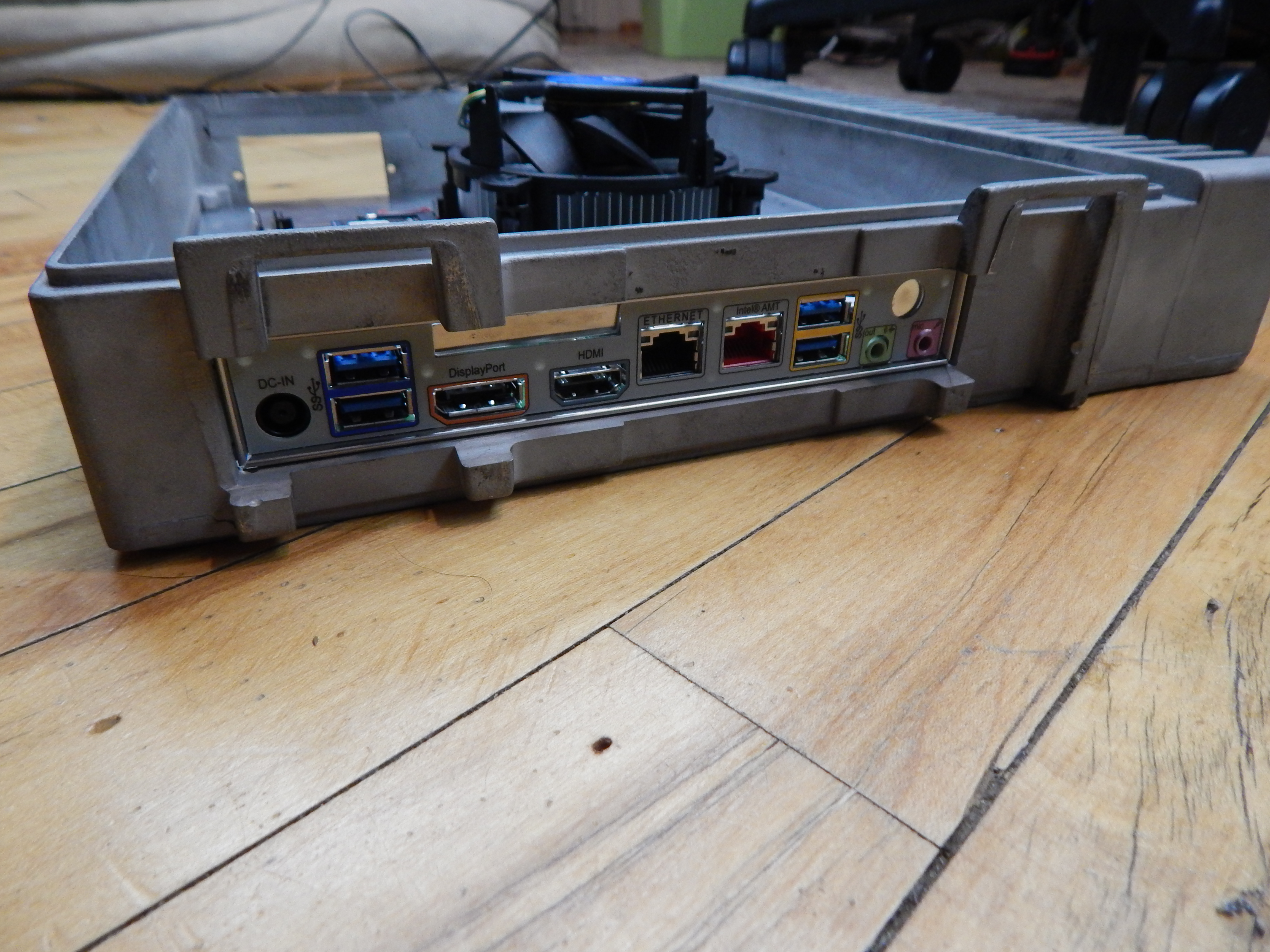
@anon45066586 The only power connections are the (large) laptop power adapter that plugs in to the rear I/O, and the SATA connector on the MB to the res pump, which I made a adapter for.