9/7/21
Hi, i’m back! With it being July, it’s time to start funtime tech nonsense!
I’m looking to build my own wifi router with some sort of SBC or mini-ITX embedded board, along with using a wifi card.
My options for the wifi card are either £30 on the intel AX210 2x2 wifi 6E card, or I just go f*** it and splurge several hundred on one of Qualcomm’s 4x4 wifi 6 cards.
The reason I so desperately am gonna get a mini-ITX embedded board is that with some of the plywood that’s lying around in my house, I can build a case for it out of that, which should be fun.
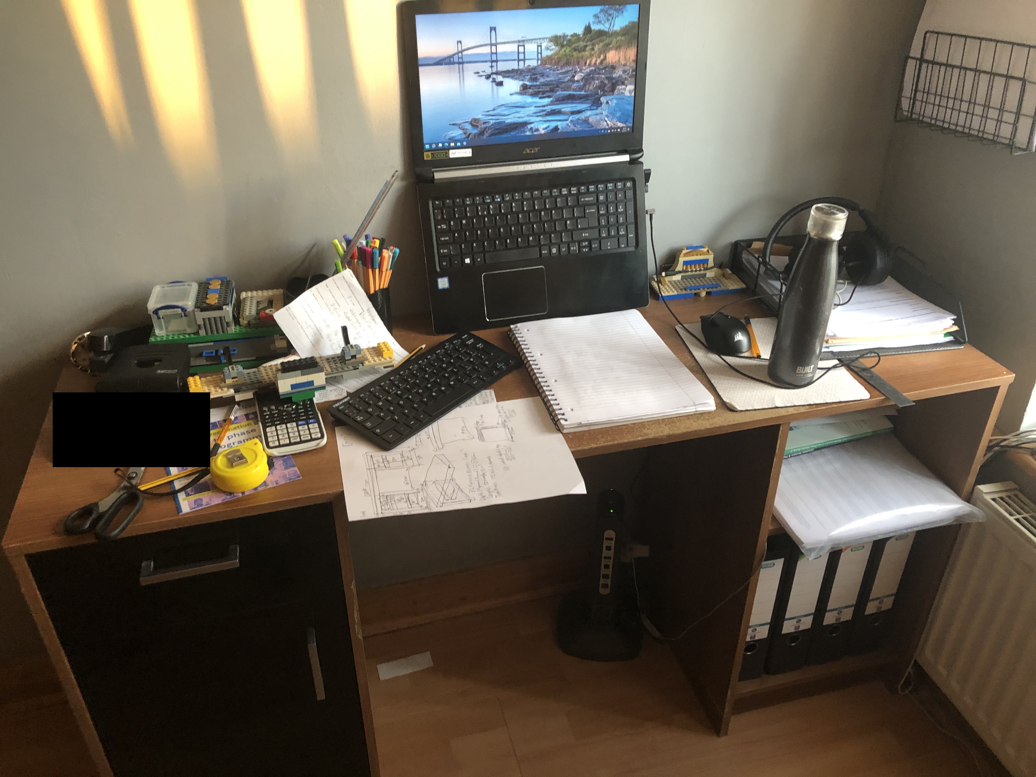
Time for a new desk. I’ve had my current one for many years, and haven’t had anything with it, with the major downside of it being it’s shallowness which has forced me into my current desk setup:
Anyway, with the plywood I have lying around, I need to do something with it, so using most of it for a new desk also seems useful.
As such, I’ll need to get a good sketchup of a new desk desgin.
So to start off with, I have here a solidworks folder containing a model of that current desk. Desk.zip (863.1 KB)
Yeah, the recipe I use is for 8 cookies (I scaled it up to 16 this time), but those ovens can typically fit 4 at a time, which is a nice small size that allows you to do a few batches.
Unfortunately, I haven’t had much time to post all the things I aimed to work on in the titular post, since I’m currently spending 8hrs a day on a factory job to earn me some cash for when I return to uni. I’ll see how much I can get done over the next month and after I quit.
PS: Don’t do this factory work if you can avoid it. It sucks, and you’re effectively a mindless drone the whole day, spending all your time and energy not learning or achieving anything exciting.
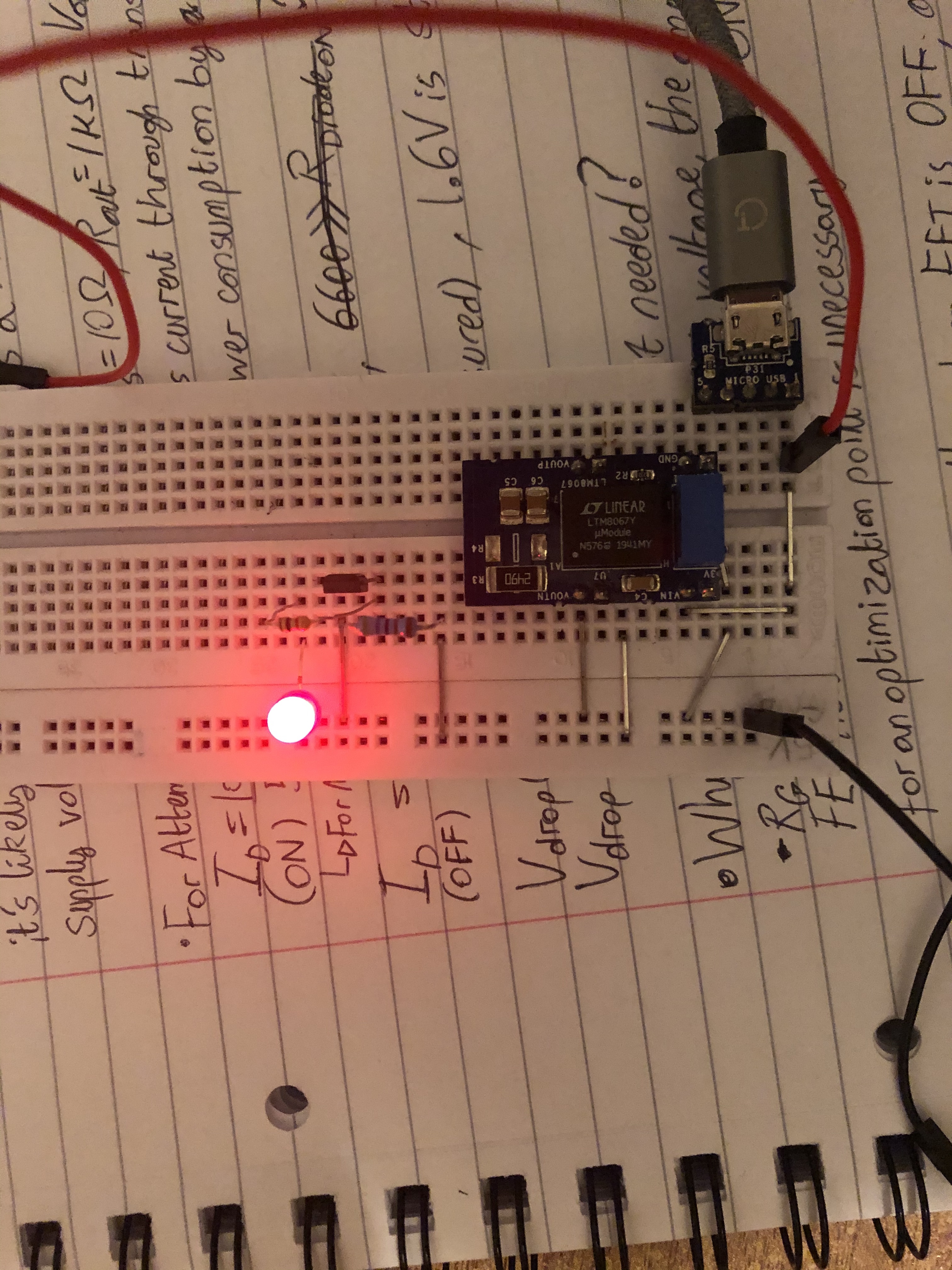
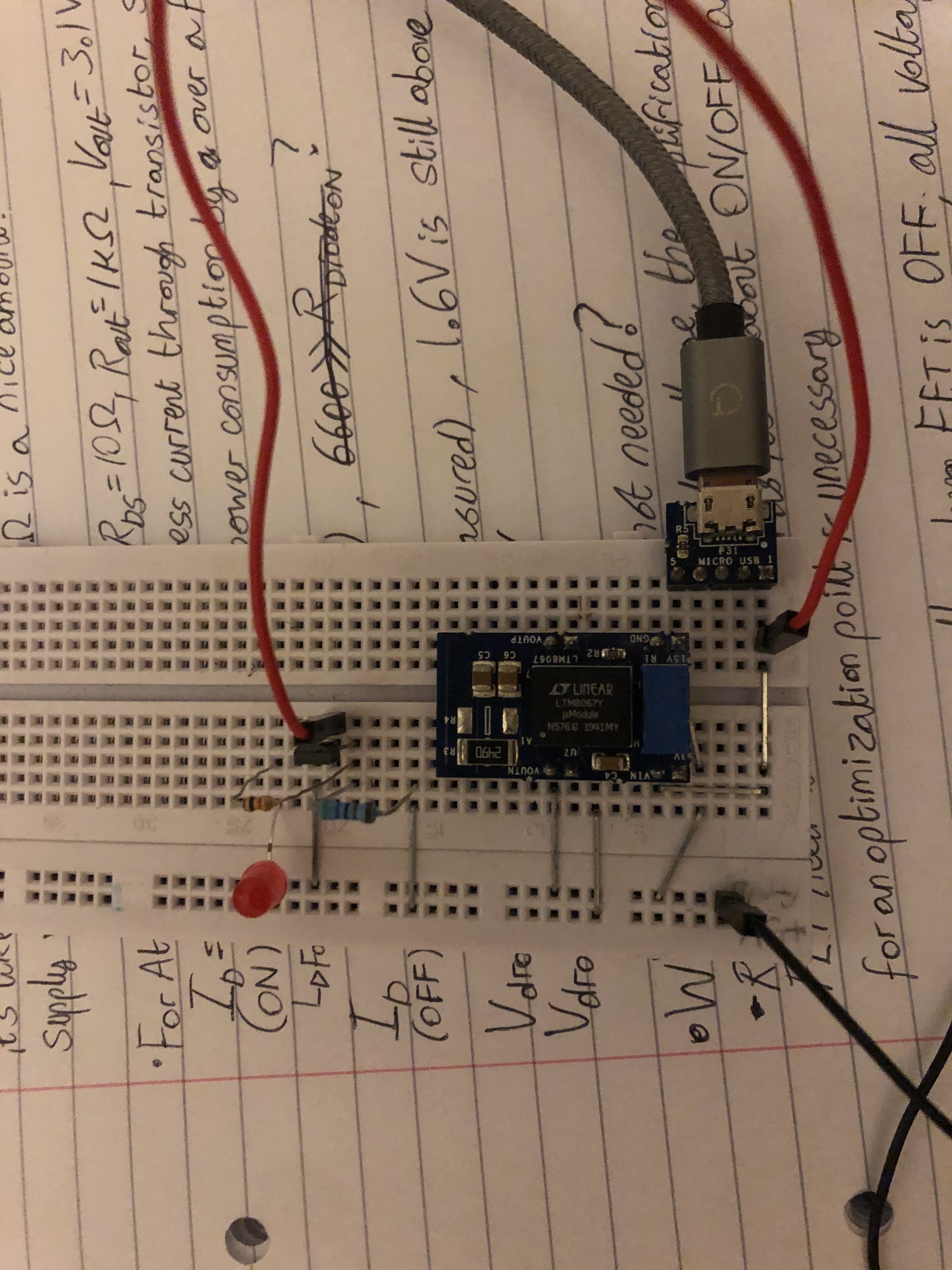
Used the linear regulator (blue and black board thingy), to take the USB 5V and use the inbuilt variable transformer (variometer? Can’t remember the name) up to 10V
So
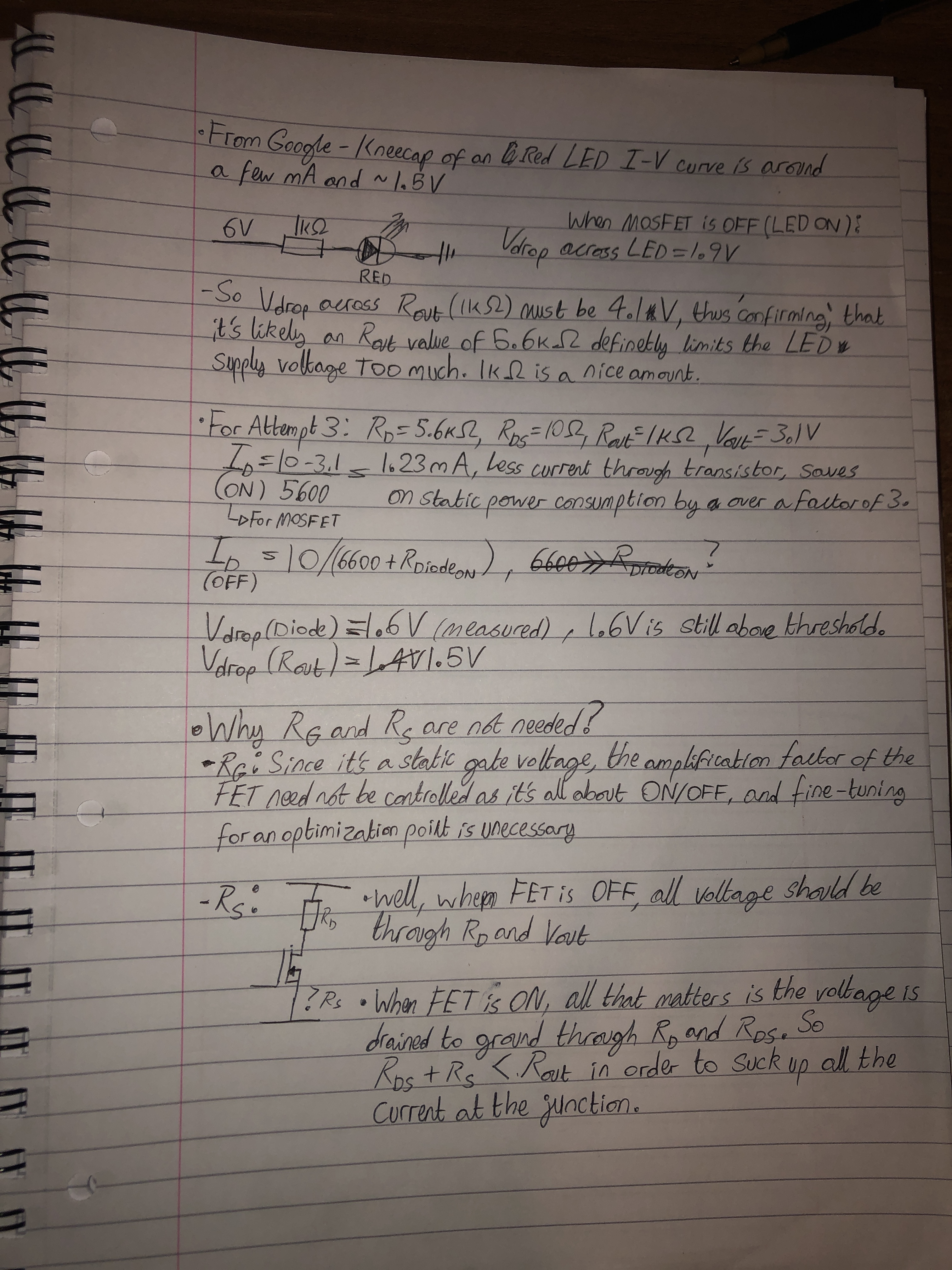
VDD = 10V
VGS = 5V
And R_D = 5.6k Ohm
LED current limiting resistor = 1k Ohm
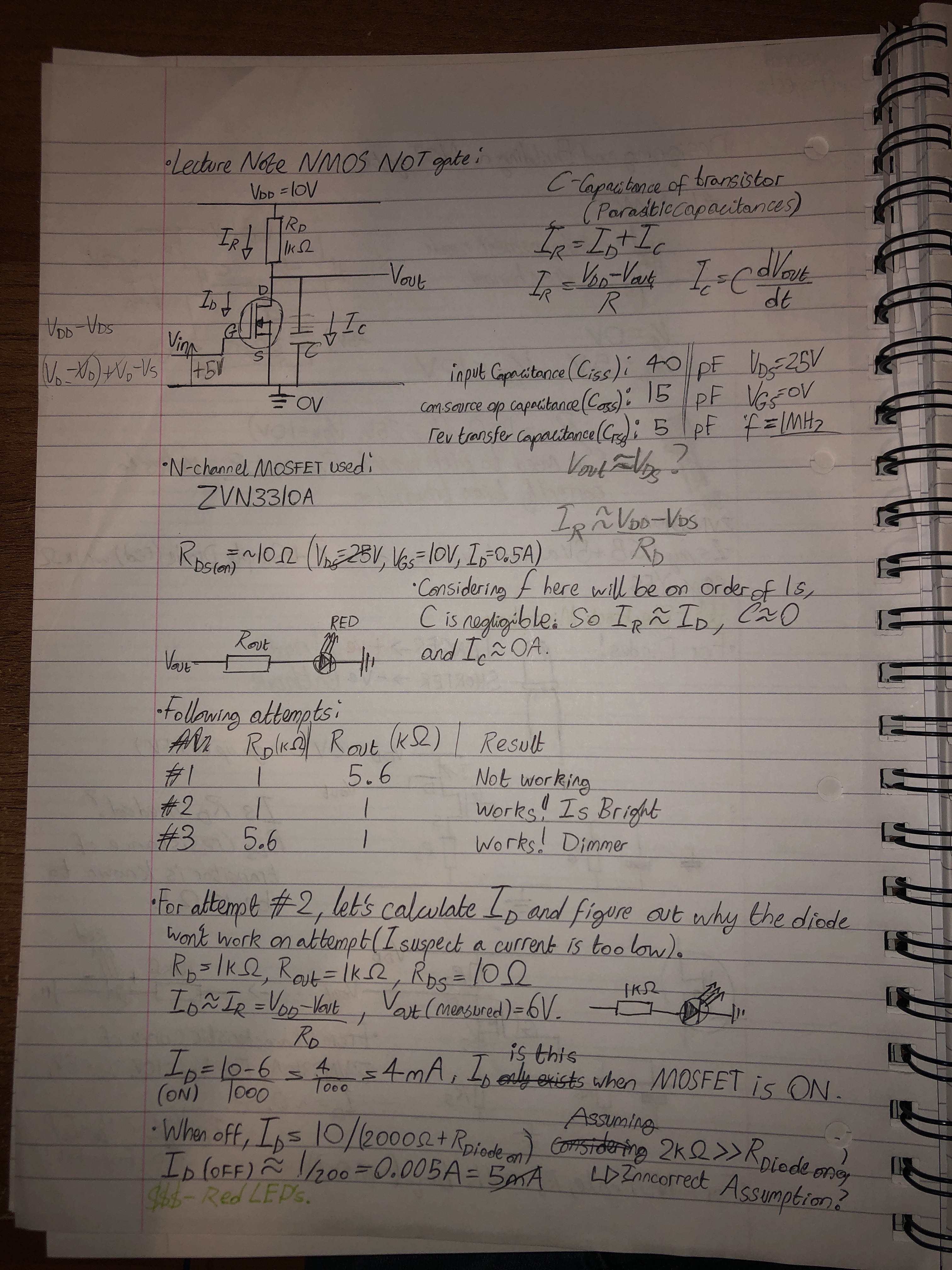
I did a CMOS one aswell (no pics), and it works good as well, switching between two distinct voltage levels, but they’re both above threshold voltage, so it lights up either way
I originally drew the diagram the same as the FET amplifiers I learnt in lectures, but acter scouring through my notes, I found another diagram that didn’t need transistors: between the ground and gate; nor the source and ground.
I later thought about why they were unnecessary and I hope below explains it well enough