Is this project still on? or dead in the water. I just really like the idea to order an I/O (RF shield) that is otherwise impossible to get cuz rare expensive mobo.
Recap: - 3D printable - Has to have RF shielding (not confirmed) - Web based - Modular design (You can place your own holes) or Mobo Selection (You can just search your mobo where a preset is already made) or both.
Like i said i can contribute with 3D models made in blender.
Almost every diy printer has buildplate of 200mm. I-am talking about sub 200 Euro printers. (almost all i3's and chinese printers, wanhou, tronxy, tarantula etc all over 180mm mostly 200mm) link
It's possible to DIY reasonably powerful laser cutters nowadays, but as of right now a small CNC machine would probably be cheaper and of similar quality.
I have this Nylon Carbon Fiber filament that would work for this type of thing as its quite strong, even when printed thin. ($66aud for 1kg if I remember correctly, from eSUN AU)
I also have some SLA printers coming, one of them has some apparently strong resin coming with it so maybe that would work also. Will have to try it out (going to be couple months before shipped however).
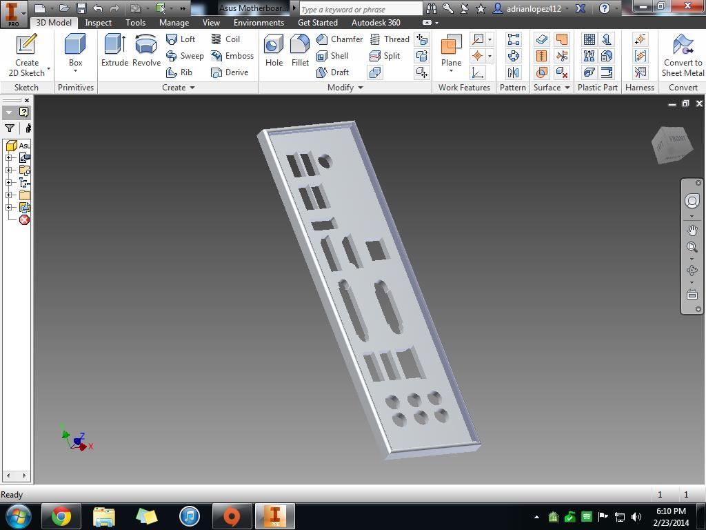
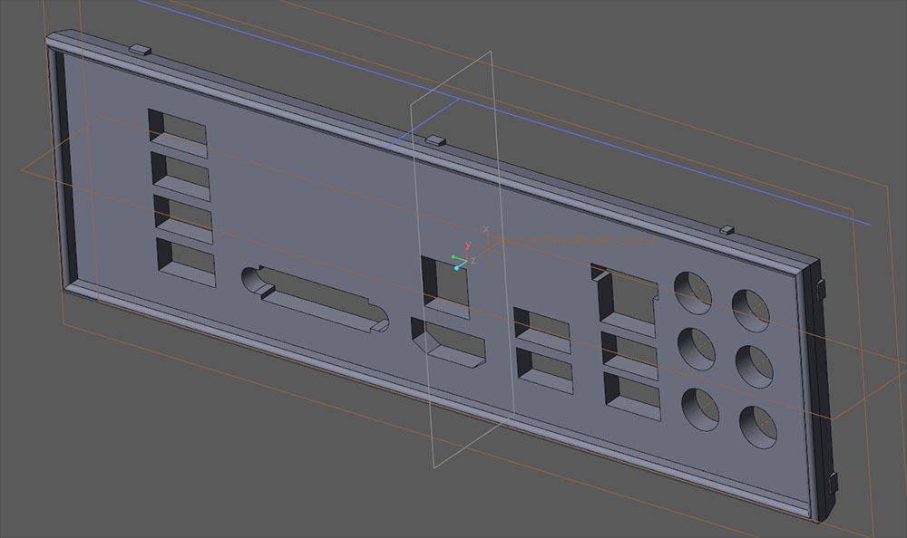
I'm off to a good start. I downloaded the pdf manual for your Gyphon Z-87 to get the I/O layout. Then I went to GrabCad and found an Asus backplate that I can modify.
My inner engineer is reluctant to share this because I know it it never going to fit without more accurate measurements. Things like this take a lot of trial fittings and errors before it is just right. A photo of the hole in your case would help.
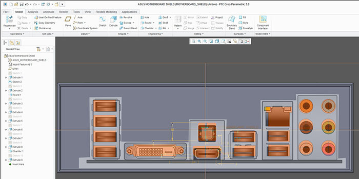
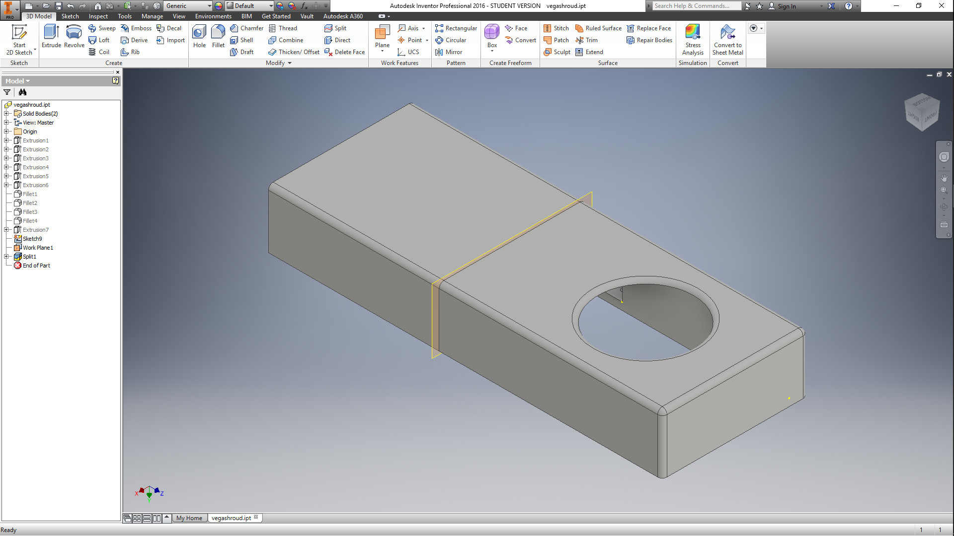
I started with the GrabCad file but I could not edit it, so I traced it. I took the picture from the pdf manual into Photoshop. Then I overlayed a screenshot from CAD and scaled the pdf to fit the 6 audio holes. Now I had to do the pain in the ass part. Faking making it fit. "That USB port doesn't quite line up in Pshop" > go back to CAD and edit the made up dimension by Hmm I'm guessing 1.5mm? > take another screenshot and drop it into Pshop > see if all the ports line up. Wash, rinse, repeat, many many times. You can also see how I made the sides a wedge shape with nubs to hold the plate in place. I figured the nubs can be easily shaped after 3D printing if they are too big.
But I had no way of knowing the dimension from edge of USB to edge of hole. The holes may fit but the sides could be off by 10mm, IDK? Maybe it would be best to print an oversized flat plate and use tin-foil tape to hold it into the case.
When I was working on getting dimensions sorted out however many months ago by far the biggest problem was lateral spacing. Getting official dimensions of each connector is pretty easy, but without knowing the spacing between the connectors it was a pain. Even a difference of 1 mm from side to side could make the plate unable to fit.
I'm sure there's a general rule of thumb about how they are spaced, but I just don't know what it is.
When I made this thing I figured the holes would be evenly spaced, but they are all over the place. My first attempt was way out due to this & I had to redraw after measuring each holes actual location.
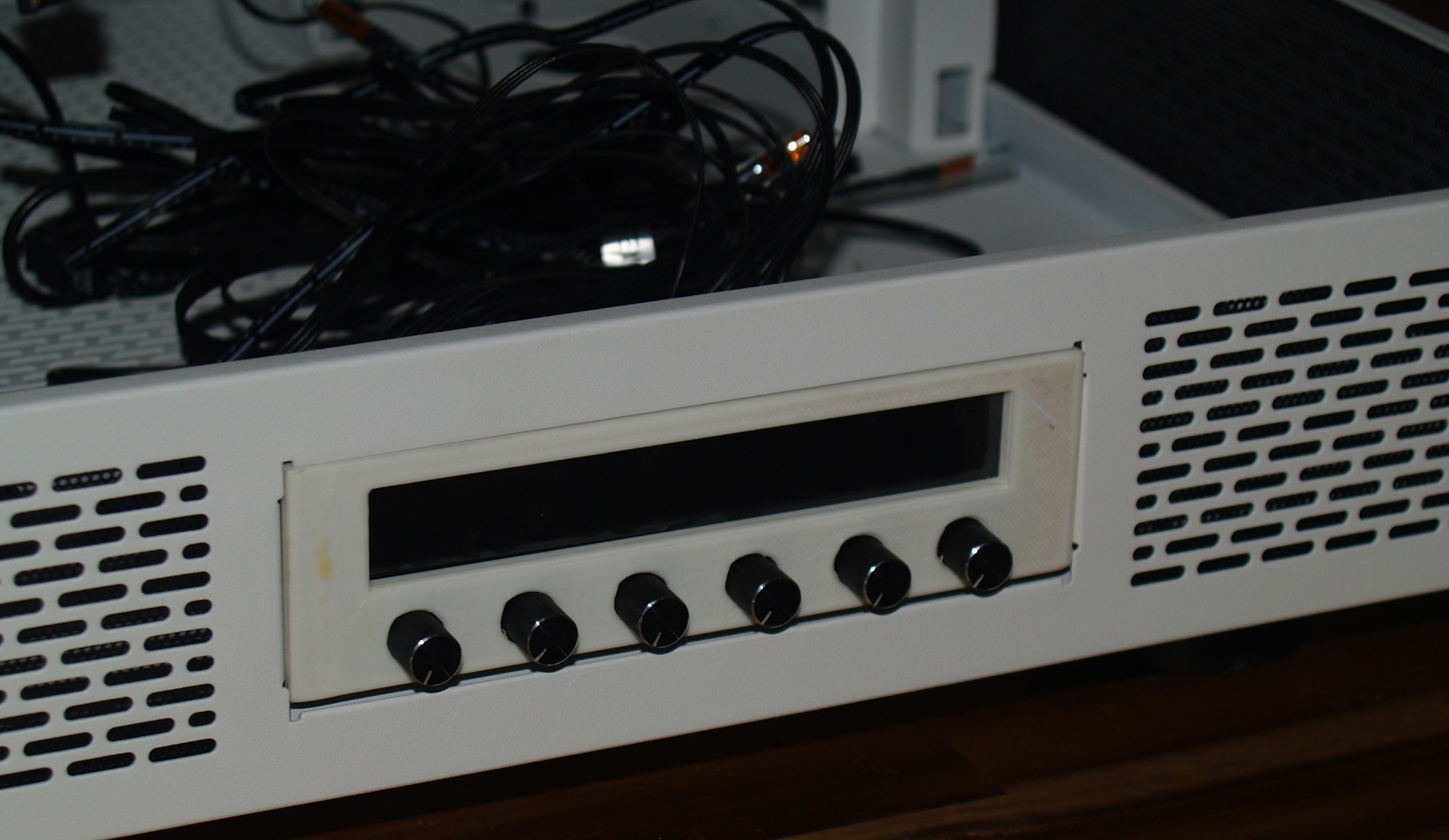
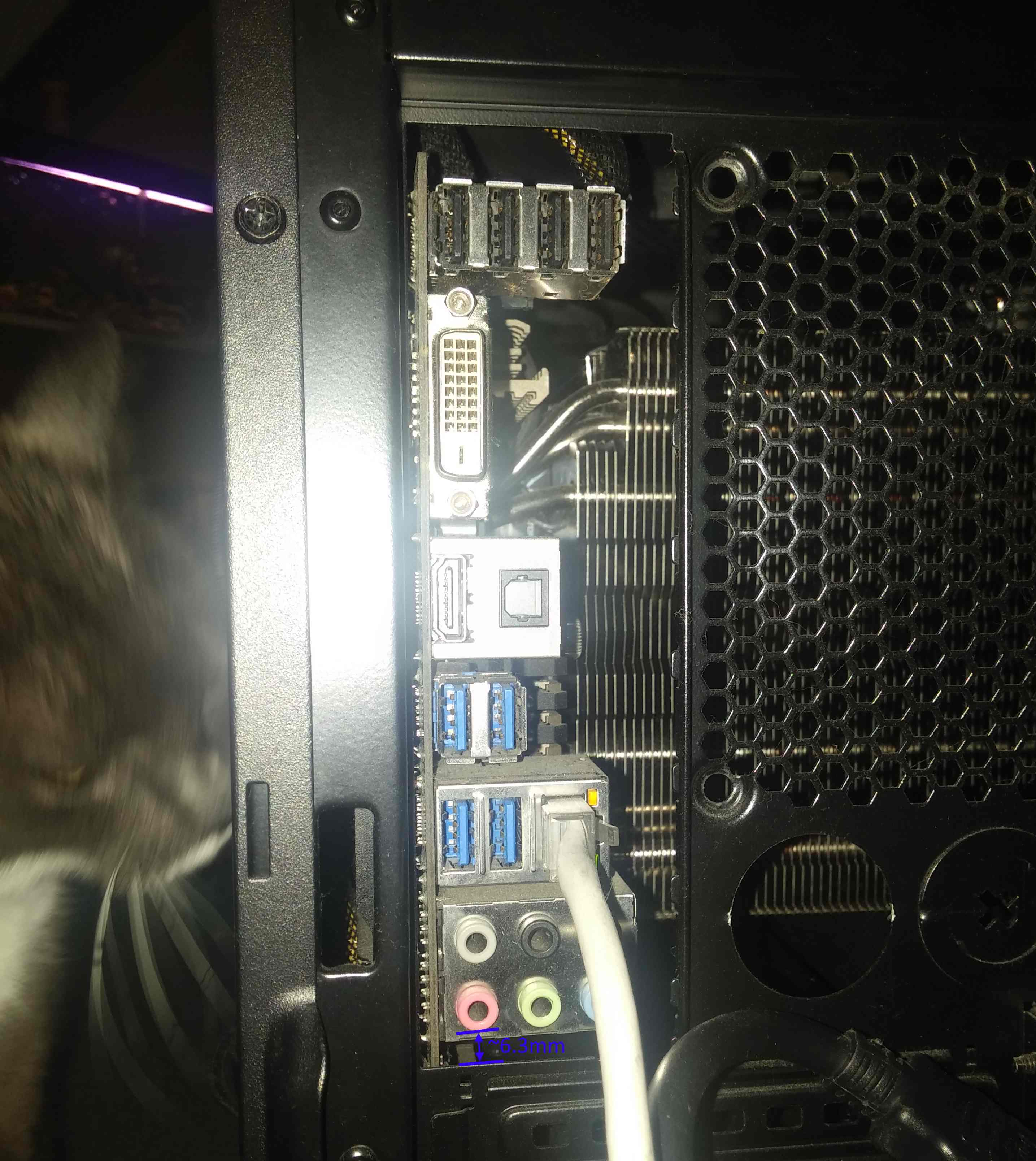
The I/O shield looks sick! great job so far. Sadly i couldn't get my calipers between the usb and my case but i did manage to measure the first audio jack.
Could you possibly make it so that i can place the i/o shield from the back? (so i don't have to dis assamble my whole pc because i-am kind of tight on time sadly. But it looks awesome!!
Good idea, no problem. Actually that solves some problems. Thanks for the pictures. But now that I know that you have a printer the best thing to do would be to print a test and measure how far I'm off. We will probably have to do that a few times. You could scale down the Z-axis to 25% or stop the print after 1mm thick as we only need a thin sheet with the holes to measure.
The other problems I am working on are as @w.meri said, getting the holes to fit will be difficult. I thought I could make each hole maybe 0.5-1mm oversized so you have some wiggle room.
The biggest problem I foresee is the thickness of the plate. My design is about 2-3mm thick now, but a sheet metal RF Shield is way thinner, almost 0mm. I doubt if 3mm will fit between the case and motherboard. 3mm doesn't have to fit in there, but then that pushes the outside surface away from the I/O. The thick plastic plate will interfere with getting the plugs into the sockets. Imagine trying to get an oversized flash drive into a crowded USB port when you can't push it home the last 2 millimeters. I can't thin the whole thing (6mm overall now) or the sides will be too thin and weak to grip the case to hold it in.
I will turn the design upside down because you plan to install the plate from the outside. I see that as a benefit. I know I have forgotten to put in the plate and wished I didn't have to take the motherboard out. Basically a thin tray with holes in it and a reinforced edge. Way easier! I wish there was a one size fits all solution where one prints a universal frame and then select LEGO pieces with various holes that snap into the frame. Or you do that in a CAD library. Wait... we're not ASUS. What is the thinnest layer that can be printed that won't fall apart? 0.5mm? 1mm?
Sorry if I sound gloomy, that's my job. We engineers are trained to ask "What is every possible way this can blow up in my clients face and then I get sued?" And I'm posting as I think. But that's how we make stuff work. Now this is my thinking phase when I like to spend time examining the initial design before I rush in to make ill advised changes. We will get there.
that's a must as the first layer can kind of smush so the holes will be ever so slightly smaller. I think 1mm oversize is a good start (many real I/O shields have about 1mm wiggle room)
Great! if you look at my case (and many others) there might be some obstruction on the top of the I/O shield so if you could clip it in place on the left and right side only it'll fit in almost every case. (top left and right assuming the i/o shield lays horizontally)
my first layer height is 0.3mm, all other layers are 0.1mm (or 0.2 if quality is less of an must have, like this project)


 because i-am kind of tight on time sadly.